13
4.2.2.1 TFT control panel operations and signals
Symbol
Description
Explanation
-
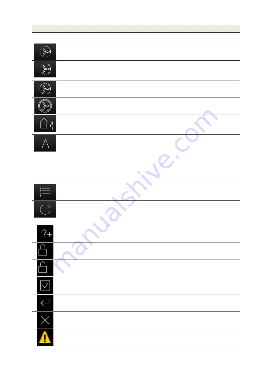
Fan speed 0 (FS0)
The fans come to a stop. This fan speed is used for the functions
automatic timer mode and un-occupied mode
Button
Fan speed 1 (FS1)
By touching this button, the smallest permanent fan speed 1 (reduced
ventilation) is set.
Button
Fan speed 2 (FS2)
By touching this button, the medium permanent fan speed 2 (nominal
ventilation) is set. This fan speed is set by the service technician
during the commissioning of the unit. A balance between supply air
and extract air is adjusted.
Button
Fan speed 3 (FS3)
By touching this button, the highest permanent fan speed 3 (intensive
ventilation) is set.
Button
Boost ventilation mode
Touching this button sets the boost ventilation mode. It initiates an
automatic timer programme in which the fan speed 3 is active for a
duration of 15 minutes (factory setting).
Button
Un-occupied mode
Pushing this button sets the un-occupied mode. For the duration of an
absence, activating the un-occupied mode sets a reduced ventilation
intensity for moisture protection. A different button must be activated
to end this function.
Button
Automatic mode
Automatic timer mode
Automatic sensor mode
The automatic mode has 2 automatic functions – automatic timer and
automatic sensor, in which the manual settings are deactivated upon
touch.
With the
automatic timer mode, different fan speeds (FS0, FS1, FS2
or FS3) can be stored for every day of the week with a duration of 15
minutes. This “fan speed weekly profile” can be configured and
individually adjusted in the menu settings/sub-menu automatic timer.
The automatic sensor mode controls the fan according to a pre-set
linear characteristic curve depending on an analogue room air quality
sensor (also a combination of CO
2
, air humidity and temperature).
Button
Menu mode
By touching this button, you enter the Information, Settings and Set-
up menu.
Button
Standby mode
The standby function sets the ventilation unit to an energy saving
mode. In the standby mode the total power consumption of the unit
drops to less than 1 W. The screen display becomes dark, but the
touch pad remains active for “waking” the system. Touching the touch
pad is enough to end the standby mode.
Button
Help
By touching this button, you enter a context-sensitive help menu. If
this key is grey, then there is no help text available.
Button
Activate key lock
By touching this button, the touch pad is deactivated except for this
button. The screen is dimmed and inactive (cleaning status).
Button
Deactivate key lock
By touching and holding this button (approx. 2-3 s) you return to the
start menu.
Button
Check mark
By touching this button, the desired or available parameter is selected
or confirmed.
Button
Enter
By touching this button, you can navigate in the various sub-menus.
Changed parameters are saved to the storage.
Button
Cancel/return
By touching this button, you move from a menu to the next higher
menu level without saving and changed data.
Signal
Messages
A blinking yellow warning triangle on the top of the right side indicates
an information or an error. Information is registered in the
Information/Current message menu and errors in the
Information/latest messages menu.
Summary of Contents for FOCUS 200 Base
Page 1: ...Translation of the original instruction manual Heat Recovery Unit FOCUS F 200...
Page 49: ...49 Dimensions Fig 43 Dimensional drawing FOCUS...
Page 50: ...50 FOCUS circuit plan Fig 44 Terminal assignment circuit diagram FOCUS...
Page 51: ...51 Master Controller terminal assignment Fig 45 Master Controller terminal assignment...


