34
adapter board must be placed in the cable ducts of the housing and fixated via the triple clip fasteners of the hinged
lid. We recommend the use of a cable type J-Y(ST)Y 2x2x0.6 LG interior cable with colour coding according to
VDE0815.
Terminal X1 (Adapter board / control panel)
Wire
Signal
X1.1
red
24P
X1.2
white
RX
X1.3
yellow
TX
X1.4
black
GND
X1.5
Aluminium coloured
Shield
Table 20: Terminal assignment for terminal X1 adapter board and terminal X1 control panel
Connecting TFT control panel
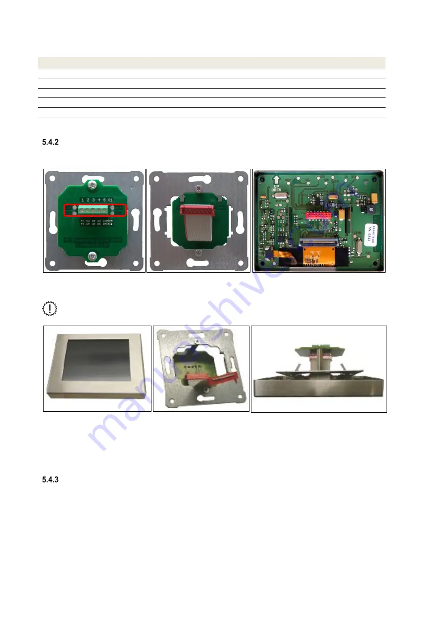
The cable type J-Y(ST)Y 2x2x0.6 must be connected to terminal X1 of the connecting board according to Table 20.
The ribbon cable connects the connecting board with the board of the TFT control membrane.
Fig. 33: Connecting board with terminal X1 on a concealed base plate; ribbon cable to the connecting board; TFT control panel
board (from left to right)
The reverse current protected plugs of the ribbon cable must be carefully inserted into the sockets
of the respective boards!
Fig. 34: Touch pad with stainless steel frame; Ribbon cable of the connecting board; touch pad with stainless steel frame latched
into the concealed base plate (from left to right)
When the control panel is ready for use, the slimmer side of the stainless-steel frame must point upwards. The
concealed base plate must be positioned in such a way that the ribbon cable of the connecting board is attached
curved downwards to the TFT control panel. The spring steel clamps mounted to the back of the touch pad clasp into
the concealed base plate and pull the stainless-steel frame securely to the wall.
Connecting several TFT control panels
Up to three TFT control panels can be connected as control panels for the ventilation unit. In terms of hardware, the
TFT control panels must be connected in parallel to the X1 terminal of the adapter board according to the wire
configuration Table 20. The TFT control panels must be commissioned in sequence and newly addressed (factory
setting standard address = 1). Addressing of the TFT control panels takes place on the software level in the
Setup/sub-menu More than one control panel.
X1
Summary of Contents for FOCUS 200 Base
Page 1: ...Translation of the original instruction manual Heat Recovery Unit FOCUS F 200...
Page 49: ...49 Dimensions Fig 43 Dimensional drawing FOCUS...
Page 50: ...50 FOCUS circuit plan Fig 44 Terminal assignment circuit diagram FOCUS...
Page 51: ...51 Master Controller terminal assignment Fig 45 Master Controller terminal assignment...


