Messages, errors and error handling
41
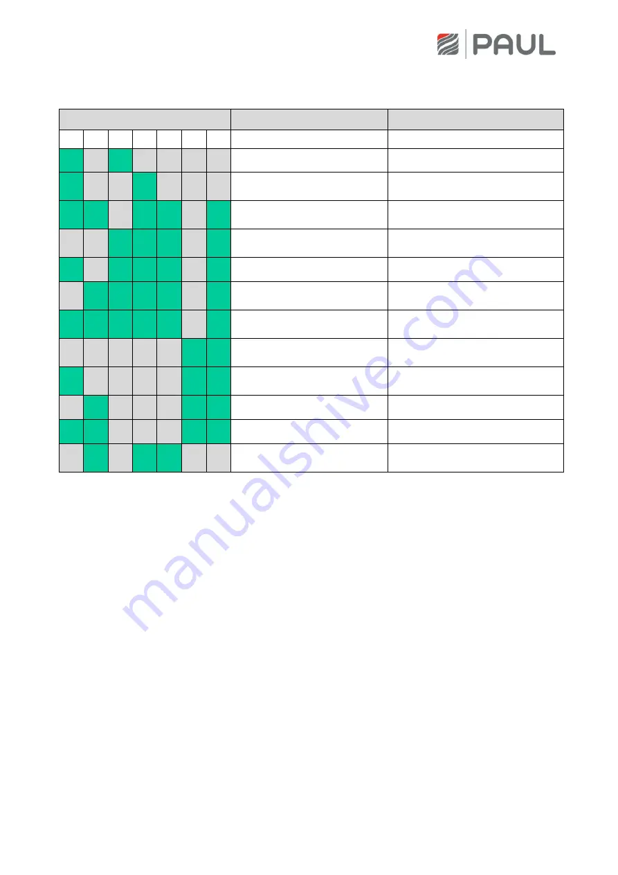
The following LED combinations for the display of the error coding marked with “x” apply:
LED combinations
Error message
Possible cause
L1
L2 L3 L4 L5 L6 L7
x
x
Supply air temperature too low Supply air temperature < setpoint
x
x
Error by-pass
No end position, by-pass not
working
x
x
x
x
x
BUS version incompatible
Software versions of the
components not compatible
x
x
x
x
Too many devices connected
Too many components connected
to the BUS
x
x
x
x
x
Fan slave not connected
Lack of BUS-communication
x
x
x
x
x
Communication error of the
fan slave
Lack of BUS-communication
x
x
x
x
x
x
Communication error of the
defroster
Lack of BUS-communication
x
x
Communication error of the
heater battery
Lack of BUS-communication
x
x
x
Comm. error flap of the
geothermal heat exchanger
Lack of BUS-communication
x
x
x
Comm. error general
Lack of BUS-communication
x
x
x
x
Heating does not switch off
Error BUS-thermostat
x
x
x
General control unit error
Lack of BUS-communication with
control unit
Tab. 4: Overview binary error coding with the LED control panel
10.2
Visualisation of errors with the TFT touch panel
The visualisation of errors with the TFT touch panel is done in the plain text display of the error message. In
the main menu Information / Last message, the last three errors that occurred are registered in compliance
with the event with date and time. In addition to this display, a yellow warning triangle flashes in the upper
right edge of the screen.


