Messages, errors and error handling
40
10
Messages, errors and error handling
The device control is equipped with an internal system for error detection. The visualisation of the
messages and the error forecast is made according to the display possibilities of the connected control
panel.
In response to an error condition, the fans are switched off and a by-pass available is closed.
10.1
Error signalling by means of the LED control panel
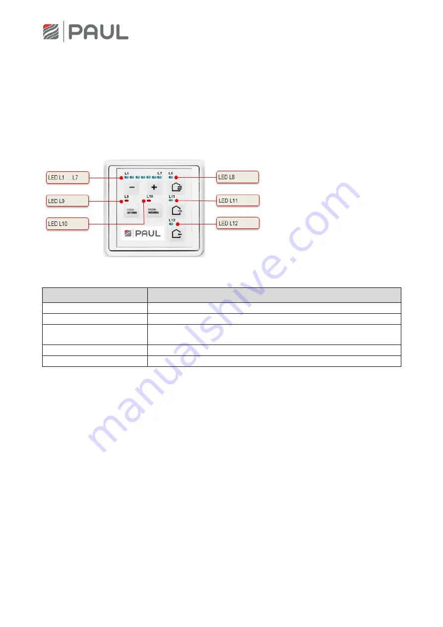
The visualisation of errors with the LED-control panel:
LED signalling
Function / meaning
L1 + L7 are lit
No external release: fan off
L8 blinks
Error sensor: Fans are switched off, by-pass closes
L8 + L11 + L12 blinks
General error, the error number is displayed in a binary form by means of
the LEDs L1 to L7 (see Tab. 4)
L11 blinks
Error fan 1 Hall: Fans are switched off, by-pass closes
L12 blinks
Error fan 2 Hall: Fans are switched off, by-pass closes
Tab. 3: Error signalling by means of the LED control panel
In addition to the signalling of the error conditions, an LED coding, which does binary present the meaning
of the error, is generated by means of the LEDs L1…L7. Information on checking / measures for a possible
elimination of the error condition are given in Tab. 5.


