background image

Status 14.07.09 

 
We reserve the right to make 
changes favouring technical 
progress.


Operating Instructions 

thermos 200 / 300 DC 

with automatic control unit


®

WÄRMERÜCKGEWINNUNG


© Paul Wärmerückgewinnung GmbH • August-Horch-Straße 7 • 08141 Reinsdorf • Deutschland  

Tel: +49(0)375-303505-0 • Fax: +49(0)375-303505-55  • E-Mail: info@paul-lueftung.de • Internet: www.paul-lueftung.de 


1

0.  FOREWORD 


READ THESE INSTRUCTIONS CAREFULLY BEFORE STARTING TO USE THE EQUIPMENT. 


The present instructions contain the information necessary for operating an installation and the mechanical 
ventilation heat recovery (MVHR) unit of the type thermos 200 / 300 DC. They also include maintenance 
and service instructions. 
This document is intended to teach you in a simple way how to use your heat recovery unit in the best way. 
If any interventions into the MVHR unit are necessary, you are recommended to call in your installer. 


The MVHR unit is subject to permanent improvement and development. So your equipment may differ in 
minor details from this description. 


We wish you much pleasure with your MVHR thermos 200 / 300 DC. 


NOTE: This document has been prepared with utmost care. However, it confers no rights 
whatsoever. We reserve the right to change all or part of the contents of this document without 
prior notice. 


1. Brief description 

 
1.1 Construction 


The compact mechanical ventilation heat recovery (MVHR) unit is delivered ready for connection. It 
comprises the heat recovery unit, the control system and the associated programmer. A 3-metre long cable 
is used to connect the MVHR unit with the control system. The link cable between the programmer and the 
control unit may have a maximum length of 15 m and shall be provided by the customer who shall also 
provide the control unit’s connection with the power supply.  
 

1.2 

Housing, heat and sound insulation 


The fan and heat exchanger box subassemblies are releasably connected by means of assembly clips. 
The entire housing consists of polypropylene (PP) foam and has no metal parts (full heat protection); the 
components and subassemblies are embedded in the heat insulating foam material. The foam is also used 
as sound absorbent material. It is recommended to connect a silencer (or 1...2 m long soundproofed flex 
hose 

 250 mm) to each of the 4 air outlets of the unit (especially to those communicating with the rooms: 

supply air and extract air). The air duct connections with the equipment must be flexible.  
 

1.3 Heat 

exchanger 


The specific design of the high-efficiency counter-flow channel-type heat exchanger, which is disclosed in 
German and European patents, is such that the plastic ducts for the extract and supply air are arranged in 
a checker board pattern, which provides a surface area twice the thermal efficiency of plate heat 
exchangers; the two fluids (supply air and extract air) are hermetically separated from one another. 
 

1.4 Summer 

bypass 


The thermos 200/300 DC MVHR unit is equipped with a motorised bypass valve and a bypass shut-off 
with safety functions for winter operation. 
 

1.5 Ventilation 

fans 


The unit comprises two electronically commutated maintenance-free 230 VAC radial fans with integrated 
power pack. The specific power consumption thus achieved is as low as 0.36 Wh/m³ (Passiv Haus 
certificate).  
The air flow rates can be varied by the user. Please note that the short presence of just a few number of 
people means low emission of CO

2

, humidity and smells into the room air and so it is possible to largely 

reduce the air flow. A second beneficial aspect is that this avoids an excessively dry room climate when 
outdoor temperatures are low (dry intake air). 


Summary of Contents for thermos 200

Page 1: ...ructions P lease keep next to the MVHR unit P lease keep next to the MVHR unit WÄRMERÜCKGEWINNUNG with automatic control unit Components suitable for Passive House Dr Wolfgang Feist Status 07 09 Paul Wärmerückgewinnung GmbH August Horch Straße 7 08141 Reinsdorf Tel 49 0 375 303505 0 Fax 49 0 375 303505 55 Deutschland ...

Page 2: ......

Page 3: ... sensor Additional programmer MVHR Installation Installation of the mechanical ventilation heat recovery MVHR unit air duct connections Power supply electric control Connection and maintenance of the condensate drain hose G Start up Readiness for operation Balancing of air flows Balancing of valves Care and maintenance by owner user General Filter change Care and maintenance by service staff Contr...

Page 4: ...pendix 1 1 Terminal assignment of control unit Appendix 1 2 Internal terminal diagram thermos 200 300 DC Appendix 2 1 External connection diagram thermos 200 300 DC Appendix 2 2 Legend of external connection diagram thermos Appendix 2 3 Cable description thermos 200 300 DC Appendix 2 4 Instructions on electrical connection of thermos 200 300 Appendix 2 5 Electrical connection of thermos 200 300 DC...

Page 5: ...customer who shall also provide the control unit s connection with the power supply 1 2 Housing heat and sound insulation The fan and heat exchanger box subassemblies are releasably connected by means of assembly clips The entire housing consists of polypropylene PP foam and has no metal parts full heat protection the components and subassemblies are embedded in the heat insulating foam material T...

Page 6: ...ack and the programmer with display and room temperature sensor The control system with the programmer controls enables the user to freely select the minimum normal and maximum ventilation steps without limitation in time But the ventilation steps can also be stored in 8 independent programs which can be assigned to the different days of the week This allows for fully automatic operation with diff...

Page 7: ...logue flow sensors to be integrated in straight tubes of the same diameter see Appendix 3 3 and Appendix 4 5 When setting the parameters it is possible to store a flow disbalance The constant flow control has to be activated and parameterised via the control unit in the menu System setup ventilation steps see User Guidance of Automatic Control Unit Section 2 5 2 4 Ground to brine to air frost prot...

Page 8: ...ed via the MVHR control system specifically equipped for this purpose A duct temperature sensor is used to limit the air temperature to 50 C because higher temperatures would cause dust particles to smoulder The duct heater is switched on or off hot water circulating pump as a function of room temperature duct temperature and temperature setpoint If the room temperature falls below the setpoint th...

Page 9: ...licone to create airtight connections After each cleaning operation every 2 years re assemble the fan box and the heat exchanger box press tightly and lock them using the blue assembly caps Leave enough space for removing and putting back the blue assembly caps 500 mm from the right and 100 mm from the rear of the MVHR unit The MVHR unit should be raised approx 200 mm from the floor to ensure suff...

Page 10: ...pped at their low point refer to Figure 2 Schematic sketch for condensate discharge line with MVHR 90 thermos Figure 1 Caution U bend traps can dry out Always refill water when starting up the unit hearing a noise from trap slurping noise noticing smells from the sewage system in the building air passes through the trap a dry trap can be recommended and is available for delivery preventing smells ...

Page 11: ... the duct install a throttle valve or a foam flow restrictor Balance the air flows at the MVHR unit if required Equal supply and extract flows vary the fan power to balance the flows the extract flow may be slightly higher than the supply flow Readjust the valves Record the values in the enclosed Air flow report 5 Care and maintenance by owner user refer to check list A 5 1 General User maintenanc...

Page 12: ...o the front 10 Re connect the MVHR unit with the power supply re energise General inspection of the MVHR unit 1 Contamination 2 Electrical safety 3 Leaktightness of condensate connection The supply and extract air passages valves should be cleaned in this context 7 Control unit 7 1 Operator comfort Standard functions 8 independent time programs can be defined by the user and assigned to any day of...

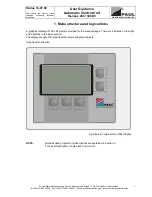
Page 13: ... Mail info paul lueftung de Internet www paul lueftung de 1 1 Menu structure and logical links A graphical display of 128 x 64 pixels is provided for the menu dialogue There are 2 buttons on the right and 3 buttons in the lower section The display accepts both graphical characters and graphic pixels Graphical construction Fig display in original size 158x125x32 NOTE All codes used programming desc...

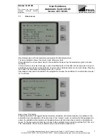
Page 14: ...ror code is indicated refer to error code table Pressing the button TA2 illuminates the display screen for 1 minute Operating a boost switch connected to the programmer causes the ventilation to run at maximum power for 15 minutes Basic menu TA5 button Pressing the button TA5 triggers manual minimum ventilation Normal and maximum ventilation or the automatic mode are adjusted in the same way In th...

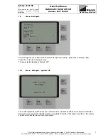
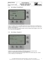
Page 15: ...and TA5 up down arrows press TA2 to select an item Press TA1 to return to the basic menu The pre selected function is System Off 1 2 1 Menu Settings 0 System Off The control system is switched off none of the sensors modules and fans is monitored or controlled Reduced power input if the standby option is available Press the TA4 button to switch on the control system which will start to run the aut...

Page 16: ...s controlled Electric duct heater ohmic heating element is controlled ISO duct heater PTC heating element is controlled Static heating elements pump is controlled Night reduction Reduction of room temperature setpoint by a given difference at a given time Required condition Control system is equipped for heater control Ventilation Controls the ventilation fans Press TA4 and TA5 up down arrows to s...

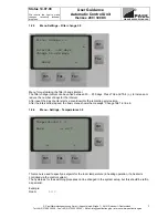
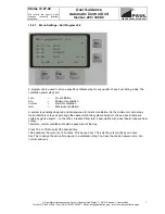
Page 17: ...50 days Press TA3 and TA4 to increase or reduce the number of days for the interval After reset the day counter starts a countdown for the remaining service time After the interval has lapsed the basic menu shows the message Change filter in line 6 1 2 4 Menu Settings Temperatures 3 0 This menu is used to specify a setpoint for the room temperature in heating operation if a heater is controlled vi...

Page 18: ...g days but to assign Program 2 to the weekend The programs can be edited by the user in the menu Programs 5 0 Use TA5 to scroll through the weekdays and press TA3 TA4 to select the desired program number Press TA1 to return to the menu Settings 4 0 1 2 6 Menu Settings Programs 5 0 In this menu you can open and adjust the eight available programs to your specific needs Press TA2 to scroll through t...

Page 19: ...ormal Normal ventilation max Maximum ventilation A system is generally designed and dimensioned for normal ventilation So the minimum or zero steps mean that there is less air exchange than assumed in the system design On the one hand there are certain hygienic aspects on the other a reduced flow rate in association with a duct heater reduces heat output Therefore normal ventilation should be used...

Page 20: ...grams will not run properly Press TA5 to scroll through the time and date until all values are set then press Save to acknowledge and store the values Save will appear on the screen when all settings have been made Press TA1 to exit the menu 1 2 8 Menu Settings Night reduction 7 0 The night reduction configuration is useful only if your unit includes a heating operated via the control system The t...

Page 21: ...eturn to the Menu Settings T intake Intake air temperature at the inlet of the unit T supply Supply air temperature at the outlet of the unit T heat Supply air temperature at the outlet of the duct heater T extract Extract air temperature at the inlet of the unit Opening any of the menus causes the unit and all extra components to be switched off So the temperatures shown here are representative o...

Page 22: ...is always programmed for the highest configuration whether or not your specific system can use and evaluate all options mentioned here System setup 9 0 9 Enable TA1 0 Frost prot heater 1 Bypass su wi 2 Brine ground HX ok TA2 3 Heat pump 4 Solar 5 Duct heater 6 Buffer max 7 Ventilation steps 8 W setting TA5 TA4 TA3 Scroll through the menu items 9 0 to 9 9 using TA4 and TA5 select an item with TA2 P...

Page 23: ...ypass su wi Bypass su wi 9 1 0 TA1 0 Temperatures 1 Servomotor ok TA2 TA5 TA4 TA3 Press TA5 to select a menu item and confirm with TA2 2 2 1 Menu System setup Temperatures Bypass su wi Bypass su wi 9 1 0 0 TA1 Bypass open if T1 T4 T4 x4 1 C T1 T4 T4 x4 2 C Hysteresis H4 C ok TA2 TA5 TA4 TA3 Press TA5 to select a value and TA3 TA4 to adjust it Example x4 1 23 0 C x4 2 19 0 C H4 1 0 K Important when...

Page 24: ...tor Bypass su wi Setup bypass su wi 9 1 1 0 TA1 min max act Bp1 100 255 100 TA2 NOTE The values are just examples TA5 TA4 TA3 Press TA5 to select a value and TA3 TA4 to adjust it min Æ Closed max Æ Open 2 3 Menu System setup Frost prot brine pump GHX valve 9 2 0 Brine GHX 9 2 0 TA1 Pump valve on open T2 x4 C or T2 x2 C TA2 Hysteresis H2 C TA5 TA4 TA3 Press TA5 to select a value and TA3 and TA4 to ...

Page 25: ...ture below setpoint and Maximum duct temperature not reached DCTH Off Room temperature exceeds setpoint or Maximum duct temperature reached Example x0 21 0 C Duct heater ON T5 20 5 C H0 0 5 K Duct heater OFF T5 21 5 C X5 50 0 C Duct heater ON T5 49 0 C H5 1 0 K Duct heater OFF T5 51 0 C Side conditions DCTH ON Thermal cut out ok only for electric duct heater with ohmic heating element Flow sensor ...

Page 26: ... needed in the system SUP EXT for positive fan adjustment e g ebm fans of series campus thermos atmos for negative fan adjustment e g Papst fans of series multi climos are used to adjust the response of the ventilation fans Fan power for each ventilation step is adjusted by means of the buttons TA3 to TA5 The fan power ratio is adjusted with the coefficient of correction e g 100 100 Equal power fo...

Page 27: ... will restart automatically after validation with TA5 2 7 Menu System setup Enable 9 9 0 Enable 9 9 0 0 Frost prot heater ON TA1 1 PTC heater OFF 2 Brine ground HX OFF 3 Bypass 1 OFF ok TA2 4 Bypass 2 OFF 5 Bypass 3 OFF 6 Bypass 4 OFF 7 Water PTC DCTH OFF SEL TA5 TA4 TA3 Press TA4 or TA5 up down arrows to scroll up or down through the menu 9 9 0 9 9 7 press TA3 to select ON or OFF The associated m...

Page 28: ... display shows x The button TA5 gives access to service menu 1 3 2 Service menu 1 Frost prot brine GHX valve Service1 FP brine GHX FHL Off T7 x TA1 x1 02 0 H1 01 0 STB FZ1 IFZ1 Brine GHX f Off T2 22 0 x2 05 0 TA2 H2 01 0 x4 25 0 TA5 TA4 TA3 This menu shows the parameters for the frost protection FP and for the FP brine pump GHX valve Frost protection FHL capital letters mean small letters mean F f...

Page 29: ...e selected k cooling mode disabled heating is not possible T0 Room temperature X0 Room temperature setpoint H0 Hysteresis für x0 x0 H0 T5 Duct temperature X5 Max duct temperature H5 hysteresis for x5 x5 H5 3 4 Service menu 3 Summer winter bypass Service3 Bp_su_wi FONKW TA1 T1 02 0 min 100 T4 02 0 max 255 x41 24 0 act 100 x42 18 0 TA2 H4 01 0 TA5 TA4 TA3 This menu shows the parameters for the summe...

Page 30: ... X X 0 30 X X X X X X X 0 45 X X X X X X X 1 00 X X X X X X X 1 15 X X X X X X X 1 30 X X X X X X X 1 45 X X X X X X X 2 00 X X X X X X X 2 15 X X X X X X X 2 30 X X X X X X X 2 45 X X X X X X X 3 00 X X X X X X X 3 15 X X X X X X X 3 30 X X X X X X X 3 45 X X X X X X X 4 00 X X X X X X X 4 15 X X X X X X X 4 30 X X X X X X X 4 45 X X X X X X X 5 00 X X X X X X X 5 15 X X X X X X X 5 30 X X X X X ...

Page 31: ...X X X X X 14 00 X X X X X X 14 15 X X X X X X 14 30 X X X X X X 14 45 X X X X X X 15 00 X X X X X X 15 15 X X X X X X 15 30 X X X X X X 16 00 X X X X X X 16 15 X X X X X X 16 30 X X X X X X 16 45 X X X X X X 17 00 X X X X X X 17 15 X X X X X X 17 30 X X X X X X 17 45 X X X X X X 18 00 X X X X X X 18 15 X X X X X X 18 30 X X X X X X 18 45 X X X X X X 19 00 X X X X X X 19 15 X X X X X X 19 30 X X X ...

Page 32: ...ings 1 Settings 2 Settings 3 Settings 4 Unit in standby Enable ON OFF Filter change Temperature setpoints Programs day Unit OFF Air heating 1 0 Filter interval 2 0 Temperatures 3 0 Programs day 4 0 Night reduction 1 1 Room Assignment of Ventilation 1 5 programs Summer bypass 1 6 to the weekdays Settings 5 Settings 6 Settings 7 Settings 8 Settings 9 Programs 1 8 Date time Night reduction Info Syste...

Page 33: ... 4 0 Unit OFF Tempe ratures 9 1 0 0 HP bypasses 9 3 0 0 Cut off temperature Servo motor 9 1 1 0 Fixing temp window for flap valve Position OFF 9 3 1 0 Define solar pump Position Heat 9 3 2 0 Position Cool 9 3 3 0 Temperatures 9 3 4 0 System setup 9 5 System setup 9 6 System setup 9 7 System setup 9 8 System setup 9 9 Duct heater 9 5 0 Buffer max 9 6 0 Ventilation steps 9 7 0 Factory settings 9 8 0...

Page 34: ... 1 0XXXXXXXXX No faults in this group 1XXXXXXXXX FAULT IN ROOM TEMPERATURE SENSOR T0 2XXXXXXXXX FAULT IN INTAKE AIR TEMPERATURE SENSOR T1 3XXXXXXXXX FAULT IN ROOM TEMPERATURE SENSOR T0 FAULT IN INTAKE AIR TEMPERATURE SENSOR T1 4XXXXXXXXX FAULT IN OUTDOOR TEMPERATURE SENSOR T2 5XXXXXXXXX FAULT IN ROOM TEMPERATURE SENSOR T0 FAULT IN OUTDOOR TEMPERATURE SENSOR T2 6XXXXXXXXX FAULT IN INTAKE AIR TEMPER...

Page 35: ...XX No faults in this group X1XXXXXXXX FAULT IN EXTRACT AIR TEMPERATURE SENSOR T4 X2XXXXXXXX FAULT IN BACK UP HEATER DUCT TEMPERATURE SENSOR T5 X3XXXXXXXX FAULT IN EXTRACT AIR TEMPERATURE SENSOR T4 FAULT IN BACK UP HEATER DUCT TEMPERATURE SENSOR T5 XX4XXXXXXX FAULT STB1 XX8XXXXXXX FEHLER STB4 XXCXXXXXXX FAULT STB1 FAULT STB4 XXX0XXXXXX No faults in this group XXX1XXXXXX FAULT FZ1 XXX2XXXXXX FAULT F...

Page 36: ...LT FZ4 FAULT IFZ1 FAULT IFZ4 XXXFXXXXXX FAULT FZ1 FAULT FZ4 FAULT IFZ1 FAULT IFZ4 XXXX0XXXXX No faults in this group XXXX1XXXXX FAULT FROST PROTECTION HEATER IS NOT DETECTED XXXX2XXXXX FAULT BACK UP DUCT HEATER IS NOT DETECTED XXXX3XXXXX FAULT FROST PROTECTION HEATER IS NOT DETECTED FAULT BACK UP DUCT HEATER IS NOT DETECTED XXXXX0XXXX No faults in this group XXXXX1XXXX FAULT SUMMER WINTER BYPASS M...

Page 37: ...ction of the control system it is possible to set up simple as well as complex control configurations covering all PAUL mechanical ventilation control variants The photograph shows a fully equipped control unit 2 Main Controller Unit HCE The HCE uses a microcontroller PIC 16 C67 having a clock frequency of 20 MHz Analogue input variables are evaluated by one or in other variants two AD converters ...

Page 38: ...rine pump on PP 8 GND 9 NPN open collector output PP power standby from HCE 10 GND 11 PWM Out fan2 extract air 12 GND 13 PWM Out fan1 supply air 14 GND 15 24P from PP 16 GND 17 24P from PP 18 GND 19 24P from PP 20 Open collector signal from PP to Controller overtemperature step 1 Controller ST_BUS pin assignments Pins 1 DB0 data bit input output 2 DB1 3 DB2 4 DB3 5 DB4 6 DB5 7 DB6 8 DB7 9 10 GND 1...

Page 39: ...protection pre heater additional switch module required Air duct heater additional switch module required Constant flow control Connector pin assignment Plug X3 1 T1 NTC temp sensor for intake air at inlet of MVHR Plug X3 2 Frost protection safety sensors STB flow sensor Plug X4 External programmer Plug X7 1 T5 NTC temperature sensor for duct heater heating circuit duct temperature or flow tempera...

Page 40: ...Technical Description Automatic Control thermos 200 300 DC Paul Wärmerückgewinnung GmbH August Horch Straße 7 08141 Reinsdorf Deutschland Tel 49 0 375 303505 0 Fax 49 0 375 303505 55 E Mail info paul lueftung de Internet www paul lueftung de 4 2 2 Controller board terminal assignment ...

Page 41: ...allation in building system refer to electrical connection instructions Fuses single phase mains 1x16 A external three phase mains 3x16 A external internal mains fuse 2A M internal on PP internal fuse for GHX valve or frost prot brine pump relay 0 1 A F on PP Output voltages 48 VDC 200 W 24 VDC 24 W 12 VDC 24 W Thermal protection 1 All loads are switched off by HCE when the 1st threshold approx 65...

Page 42: ...tion of the power pack take care to ensure the individual phases are loaded symmetrically Use a 3 core cable for direct load connection to connector 2 of the power module inverted 3 pole plug To select the function for the module it is necessary to place two jumpers for the start up both jumpers must have the same position in the male connectors Functions 1 Frost protection 2 Back up heater electr...

Page 43: ...eutschland Tel 49 0 375 303505 0 Fax 49 0 375 303505 55 E Mail info paul lueftung de Internet www paul lueftung de 7 4 1 Terminal connection plan for switch module Switch module 2 1 KW 230 V INPUT from voltage distribution to power pack 230 V OUTPUT to electric load L N PE Pmax 2100W x2 V dist Input X1 Lx N PE Lx N PE 1 8 8 1 1 Frost protection heater 2 Duct heater 3 Heating rod 4 Storage charging...

Page 44: ...tion The programmer can be used to view enter or change any parameters of the mechanical ventilation control unit The programmer offers menu dialogues so all settings are self explaining There are two access modes one for the user and one for the service staff The user can just make a limited number of settings and validations only The system setup menu allows the service staff to change any param...

Page 45: ...HX valve frost protection brine pump T2 Outdoor temperature x2 min temp GHX valve OPEN pump ON x4 max temp GHX valve OPEN pump ON H2 hysteresis for x2 and x4 x4 Æ Menu 9 2 0 Setup GHX valve brine pump Valve OPEN pump ON T2 x4 x2 Æ Menu 9 2 0 Setup GHX valve brine pump Valve OPEN pump ON T2 x2 Plausibility range of the temperatures T0 T5 30 95 C Setting parameter specifications X0 20 0 C 00 0 35 0 ...

Page 46: ......

Page 47: ......

Page 48: ......

Page 49: ...r is switched on and off by the control unit Sensor equipment for electric back up duct heater Comprising flow indicator thermal cut out and duct temperature sensor for monitoring the electric duct heater Power supply Depending on system configuration single to three phase as a function of the connected loads electric duct heater frost protection heater with a maintenance service or master switch ...

Page 50: ...tion appropriate length to be laid by customer l Sensor line T5 control unit Copper strand with PVC insulation LiYY 2 0 5mm 5V DC Sensor mit Kabel und Stecker werksseitig vorkonfektioniert nur Sensor with cable and plug prefabricated insert only when using a heating circuit whose pump is operated by the control unit 5m m Control line Control unit flow sensors Control line YSLY JZ 4 0 5mm 24V DC Ap...

Page 51: ...ext to each other or in the same cable duct because this might cause parasitic induction and disturb the sensor elements A minimum distance of 20 cm 8 inches is recommended Install the control unit in a way to ensure there is no heat build up and sufficient space for service access Never enclose or bury the control unit e g no flush mounting The internal temperature sensor of the programmer must r...

Page 52: ......

Page 53: ......

Page 54: ......

Page 55: ......

Page 56: ......

Page 57: ......

Page 58: ......

Page 59: ......

Page 60: ......

Page 61: ......

Page 62: ......

Page 63: ......

Page 64: ......

Page 65: ......

Page 66: ......

Page 67: ...on single phase 230V 50Hz three phase 3 x 230V 50 Hz with frost protection and back up duct heater options Central control unit LxWxD mm 340x300x80 or 340x300x140 with frost protection and back up duct heater options Enclosure IP 44 MVHR unit IP 20 control unit Protection Class I acc to EN 60335 Weight 35 kg Notes Install the MVHR unit upright in a frost free place preferably 10 C Never lay contro...

Page 68: ...power input below 2 W manual adjustment of ventilation steps off minimum normal maximum programmer can be installed in any place in the house ventilation steps programmable in 1 increments 30 100 of maximum fan power adjustable balance between supply and extract air fans filter monitor for change interval freeze protection for downstream hot water duct heater Options with extra price for accessori...

Page 69: ... filters in fresh air pipe Suctioning in of outside air also in the soil heat exchanger Quarterly Year I II III IV 200 201 201 201 201 4 Exhaust hood Clean grease filters every 6 8 weeks with hot water for rinsing Change activated carbon filter only in the case of a circulating air hood every 4 months Quarterly Jahr I II III IV 200 201 201 201 201 Simplified formula for determining heat recovery r...

Page 70: ...nd heat exchanger c at extract air valves d check filter change intervals by inspecting the records of the tenant owner e record any filter change in writing 3 Check intake air ducts for contamination on a random basis also in the ground heat exchanger 4 Check silencers sound attenuators a at the MVHR unit b in the ventilation system if accessible c at overflow passages openings e g doors partitio...

Page 71: ...13 Check insulation visual examination a damage b moisture penetration c connection point at MVHR unit d line to valve connection 14 Check fire dampers if any a inspect test report b latch and trigger mechanism check for contamination and reversible function c change trigger element and check for smooth action d functional check of position indicator 15 Measurements and recording of measured data ...

Page 72: ... Very dirty Fan speed ratio clean extract supply air Supply air Ventilation step Project Data Measurement data Valve No Room description m h m s m h m s mm Extract air Ventilation step Project Data Measurement data Valve No Room description m h m s m h m s mm Pel W 2 fans The control system of the MVHR unit has been inspected 1 The volumetric air flow is measured during normal MVHR operation 3 as ...

Reviews: