Fotoelektrik Pauly – Light barriers
E_52692 Ref. 2019-29
10/24
Fotoelektrik Pauly GmbH, Wahrbrink 6, D-59368 Werne, T: +49 2389/402 27-70, F: +49 2389/402 27-77
http://www.fotoelektrik-pauly.de, eMail: info@fotoelektrik-pauly.de
The requisite reflector plates on the reverse are available in different sizes. The format to be used
for the reflector is determined by the clearance distance and the resultant triangulation angle.
For clearance distance
reflector area (width x height)
Model
up to 25 m
400 mm x 100 mm
4R100BL(AF)
up to 50 m
900 mm x 200 mm
18R100BL(AF)
The reflector comprises a carrier plate with individually mounted reflector elements on it. The
reflector elements are fastened with screw connections that cannot be loosened with conventional
tools. Moreover, due to their design, the reflector elements cannot get be misplaced. The special
design of the reflector plate means that the reflector elements are protected against strong
pollution deposits and overflowing water. It is not possible to dismantle the reflector using
conventional tools without damaging it.
4.3 Description of function
4.3.1 Triangulation triangle
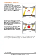
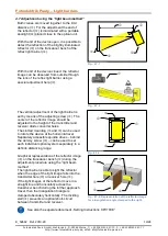
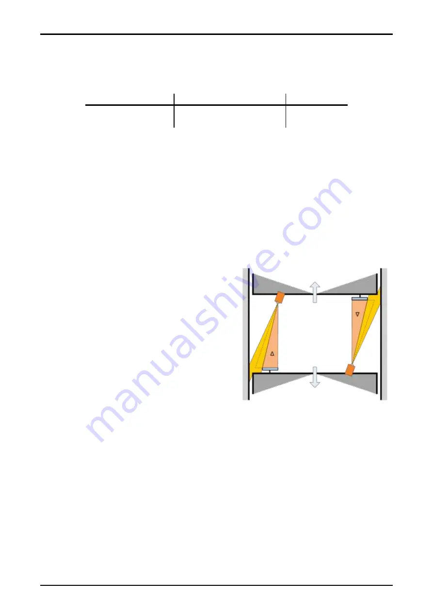
The clearance distance is determined using the
triangulation method. For this purpose, the high
performance reflex light barrier must be aligned at an
angle to the direction of movement of the crane
towards the reflector affixed to the other crane. The
right-angled triangulation triangle is formed as
follows:
(when sighted from the light barrier)
from the distance between the two cranes
–
connecting line between the installation location
of the light barrier and the left reflector
edge = adjacent side to angle >
< and
from the width of the reflector = opposite leg to
the angle >
< and
from the outer light cone form the reflex light
barrier = hypotenuse of the right-angled triangle.
Fig.: 4.3.1
Triangulation triangle
Reflex-light barrier
Crane 2
Crane 1
Reflector


