Fotoelektrik Pauly – Light barriers
E_52692 Ref. 2019-29
15/24
Fotoelektrik Pauly GmbH, Wahrbrink 6, D-59368 Werne, T: +49 2389/402 27-70, F: +49 2389/402 27-77
http://www.fotoelektrik-pauly.de, eMail: info@fotoelektrik-pauly.de
4.5 Assembly
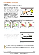
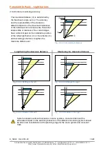
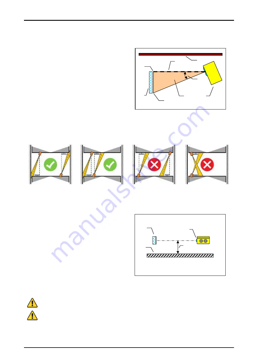
4.5.1 Horizontal arrangement of the triangulation triangle
Reflector (
) and light barrier-CPV1038 (
)
are mounted horizontally. The triangulation
triangle (
) then lies in the space horizontally.
is mounted onto the crane using the JF57S
adjustment flange. An imaginary line (
) that
runs parallel to the crane track (
) connects
on the right edge of the reflector (
). The
angle (
) of the triangulation triangle should
be selected such that the
is pointing
towards the left reflector edge when the limit
distance is reached (
) (see also chapter on
“adjustment”).
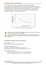
The triangulation triangles must be designed in such a way that the light barrier optics do not
look into each other, directly or via reflections. Examples:
Fig.: 4.5.1-2:
Proper arrangement
Fig.: 4.5.1-3:
Proper arrangement
Fig.: 4.5.1-4:
Wrong arrangement
Fig.: 4.5.1-5:
Wrong arrangement
Note to fig. 4.5 1-3: The distance between the applied outer edge of the device and the reflector
must be at least 200mm.
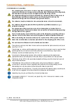
The Reflector and CPV1038 must be mounted
at the same height. This means that the
middle of the reflector (
) must be positioned
at the same height (
) as the middle of the
lens system of CPV1038 (
). The height of
both parts should be taken from a common
reference point (
).
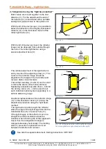
It is essential to ensure that both optical systems can still view the reflector when both
cranes have been moved together up to buffer distance!
Mount the reflector close to the edge of the crane bridge. Avoid blocking the visible area
of the reflector.
Fig.: 4.5.1-1: Example of a triangulation triangle
clamped to the left
Fig.: 4.5.1-6


