background image

Fotoelektrik Pauly – Light barriers  

E_52692   Ref. 2019-29 


17/24 

Fotoelektrik Pauly GmbH, Wahrbrink 6, D-59368 Werne, T: +49 2389/402 27-70, F: +49 2389/402 27-77 

http://www.fotoelektrik-pauly.de, eMail: info@fotoelektrik-pauly.de 

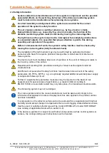
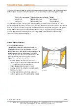
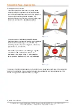
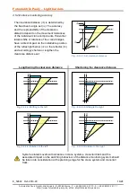
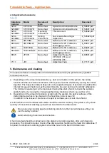
4.5.3 Taking the tolerances into consideration with respect to clearance distance 

The very high performance of the system facilitates “tolerant” functional behaviour. However a 
certain tolerance in terms of distance behaviour must be taken into account for the very reason of 
this high performance in order for perfect, planned functional behaviour of the system to be 
guaranteed at all times in the long term (e.g. aging). For this reason the following possible 
tolerances must be taken into consideration from the start. 


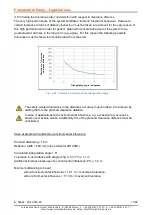
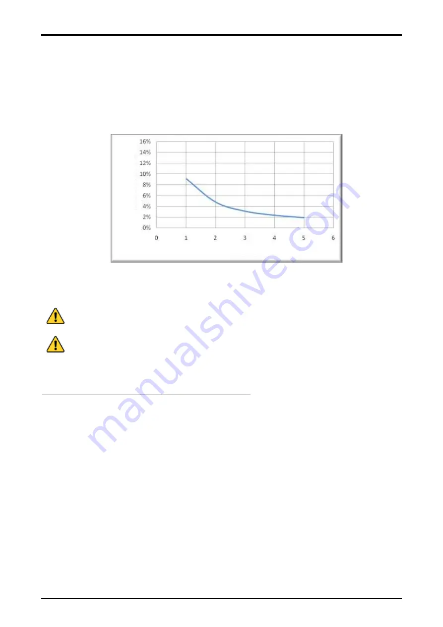
Fig.: 4.5.3: Tolerance in relation to the triangulation angle


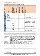
The safety-related tolerances in the distances accuracy must be taken into account by 
adding them to the planned clearance distance. 


In case of applications with environmental influences, e.g. excessive fog, excessive 
steam or excessive smoke, additionally 8% of the planned clearance distance must be 
considered  


Case example with and without environmental influences: 
 
Planned distancing = 15 m 
Reflector width = 400 mm (crane reflector 4R100BL) 
 
Calculated triangulation angle 1.5° 
Tolerance in accordance with diagram fig. 4.5.3: 7% 

 1,1 m 

Additional tolerance because of environmental influences: 8% 

 1,2 m 

 
Minimum distancing to be set 

without environmental influences = 16.1 m + movement tolerance. 
with environmental influences = 17,3 m + movement tolerance. 


D

e

v

ia

ti

on 

in

 %

 f

ro

m

 t

he


c

le

a

ra

nce

 d

is

ta

nce


Triangulation angle in degrees 

Summary of Contents for CPV1038

Page 1: ...PL c SIL 1 in acc with EN ISO 13849 and EN 62061 Two optical systems in one enclosure Two adjustable independent clearance distances Clearance distance up to 50 m High performance in terms of detection Pollution warning Anti Sabotage system Integrated test system a highly dynamic process reproduces the light reflected by the reflector Safe mounting of reflectors o Collision protection o Distance m...

Page 2: ...ormation on this technical description 9 4 2 Device description 9 4 3 Description of function 10 4 3 1 Triangulation triangle 10 4 3 2 Approach movement 11 4 3 3 Continually self testing 12 4 3 4 Possible movement of the crane 12 4 3 5 Movement of the crane is stopped 12 4 4 Pollution control function 13 4 4 1 Principle 13 4 4 2 Pollution example 13 4 4 3 Pollution Indicator meaning of the differe...

Page 3: ...tslevel Safety Integrity Level 1 gemäß DIN EN 62061 according to DIN EN 62061 Sicherheitskategorie Safety category 2 Performance Level c MTTFd a 86 gemäß DIN EN ISO 13849 1 according to DIN EN ISO 13849 1 Bezeichnung General description Optical Anti Collision Device Typ Type CPV1038 01 CPV1038 01 R 2M20 i 5269M01x 0393 Seriennummer Serial number Baujahr Year of manufacture Reichweite Range 1 25m V...

Page 4: ...c control systems 1 4 Definition of symbols Must follow Critical information This symbol describes safety warning of dangerous situations and indicates necessary measures and or appropriate precautionary measures Failure to comply can result in death or property damage Must know Important information This symbol describes e g situations that could damage the product or devices in its vicinity and ...

Page 5: ...he other crane opposite crane When used as a distance monitoring device a risk triggering approach of cranes is detected At least one device is required for each crane and the corresponding reflector is positioned at the opposite wall crane 2 3 Incorrect use and foreseeable misuse It is not permissible to use the device in any manner that deviates from the contents of the operating instructions or...

Page 6: ...essional expertise to install electrical devices on crane systems The device must be immediately taken out of operation in the event of damage or leaks in the housing cable or line entries Requirements resulting from provisions relating to cranes must be applied under all circumstances All different components with safety functions must be taken into account of the safety parameters PL PFHd MTTFd ...

Page 7: ...O 13849 1 PFHd h 1 6 61 x 10 7 MTTFd a 86 nop n a 8760 CCF 95 Mission time TM a 20 Maximum clearance distance 50 m 25 m Optical systems 2 Safety related tolerance of the systematically distancing accuracy Maximum 9 in accordance with diagram fig 4 4 3 Safety related tolerance of the distancing accuracy due to environmental influences Additional 8 by reason of environmental influences e g fog steam...

Page 8: ...ark switching Housing Cast aluminum Protection mode IP65 protection against dust and jets of water Weight 5000 g without adjustment flange Operating temperature 25 C 60 C non condensing Climatic conditions in acc with EN 60721 3 3 1995 table 1 max relative humidity d 95 max solar radiation j 700W m Condensation m none Wind driven precipitation n none Formation of ice and frost including freeze tha...

Page 9: ...ight which impact on the internal receiving unit through the receiving lens The external test units continuously simulate the light reflected by a reflector A highly dynamic signal processing procedure evaluates the rays of light pulses received This evaluation means that the distance monitoring system is fail safe shock resistant resistant to external light and stable When the set clearance dista...

Page 10: ...al design of the reflector plate means that the reflector elements are protected against strong pollution deposits and overflowing water It is not possible to dismantle the reflector using conventional tools without damaging it 4 3 Description of function 4 3 1 Triangulation triangle The clearance distance is determined using the triangulation method For this purpose the high performance reflex li...

Page 11: ...ed off pre disconnection If the approach is continued and the second set clearance distance is reached the second reflex light barrier illuminates the edge of the reflector The switching outputs of the second system in the reflex light barrier are switched off The safety related sw itching outputs sw itched off and crane travel is brought to a halt The cranes stops with a safe distance from each o...

Page 12: ...erequisite The reflector is undetected The actual distance between the cranes is greater than the set clearance distances The beams of the reflex light barriers goes past the reflector There are no optical or electronic faults Effect The crane is cleared for movement For each system two safety related relays are switched on and these signal the clearance for crane movement through the closed NO co...

Page 13: ... detection The weakening of a specific signal level here also leads to a pollution warning signal The pollution on the external test unit of the light barrier will be much more sensitively evaluated than the pollution on the reflector The pollution warning signal is displayed with the VK relay The triggered relay means that there is a pollution which must be eliminated as soon as possible where th...

Page 14: ... off No pollution on the reflector Less than V level off on on Pollution on the reflector OR incomplete reflector view in the pre switching mode off off on Pollution on the reflector OR incomplete reflector view in the main switch off mode Legend Explanations V level Pollution warning level default setting by manufacturer LB Light barrier Pollution on the reflector The Pollutants on the reflector ...

Page 15: ...on triangles must be designed in such a way that the light barrier optics do not look into each other directly or via reflections Examples Fig 4 5 1 2 Proper arrangement Fig 4 5 1 3 Proper arrangement Fig 4 5 1 4 Wrong arrangement Fig 4 5 1 5 Wrong arrangement Note to fig 4 5 1 3 The distance between the applied outer edge of the device and the reflector must be at least 200mm The Reflector and CP...

Page 16: ...tations of the crane bridges have a direct impact on the installation position of the reflex light barrier or the reflector and accordingly shorten or lengthen the clearance distance set Lengthening the clearance distance Shortening the clearance distance System related movement tolerances in crane systems crane rail track and the associated impact on the switching behaviour of the distance monito...

Page 17: ...into consideration from the start Fig 4 5 3 Tolerance in relation to the triangulation angle The safety related tolerances in the distances accuracy must be taken into account by adding them to the planned clearance distance In case of applications with environmental influences e g excessive fog excessive steam or excessive smoke additionally 8 of the planned clearance distance must be considered ...

Page 18: ...paration distance When calculating the clearance distance the reaction time of the system must be taken into consideration as decisive parameter for the stopping path of the crane The set clearance distance must be tested and recorded The reflector centre on the other crane must be situated at the optical device lens level see Fig 4 5 1 6 The devices on a crane and the adjacent crane must be mount...

Page 19: ...age should be adjusted to the height of the transmitter and receiver diode converter holes The slotted mounting and can be used to rotate the device at the horizontal level Separately accessible spindle drives behind the dummy screw can be used to set each individual optical system separately to a definite distancing range Graphical representation of the reflector image on the transducer bench dur...

Page 20: ...Version AC L1 Version DC 24 V 2 N 0V Supply voltage Version AC N Version DC 0 V PE PE Protective earth conductor 3 4 NO11 Make contact 1 normally open contact of system 1 safety related 5 6 NC11 NC12 Break contact of system 1 7 8 NO12 Make contact 2 normally open contact of system 1 safety related 9 11 NOv COMv NCv Pollution warning changeover contact 12 13 NO21 Make contact 1 normally open contac...

Page 21: ... crane type e g EN 15011 The external power supply has to fulfil the rules for low voltage with safe isolation SELV PELV in accordance with EN 60204 1 A protective earth connection is essential for protection against electric shock from exposed conductive parts It is not allowed to use the normally closed contacts NC11 NC12 system 1 and NC21 NC22 system 2 also the change over contacts NOv COMv NCv...

Page 22: ...sonnel a Depending on the amount of pollutants e g dust accumulation in the system the safety function and the set clearance distance of the system must be checked by moving the cranes together The inspection interval depends on the expected degree of pollution A suitable time interval for regular checking must be determined by the user and must be strictly adhered to The minimum requirement is th...

Page 23: ...e 2006 42 EC The product may only be put into operation by competent personnel acting in compliance with the supplied documentation In particular it is mandatory to observe the safety and installation instructions and the instructions for the use in accordance with the intended purpose This declaration is no longer valid if the Product is modified without our consent Additionally applied directive...

Page 24: ... 230VAC 6801 4R100BL Reflector for 25 m distance 6801A01 4R100BLAF Reflector for 25 m distance anti fogging version 6802 18R100BL Reflector for 50 m distance 6802A01 18R100BLAF Reflector for 50 m distance anti fogging version 8655 JF57S Adjustment flange for CPV1037 CPV1037 01 CPV1038 and CPV1038 01 7111 JH1 Adjustment help Order data Model power supply Example CPV1038 230VAC D 59368 Werne 2019 04...

Reviews: