Fotoelektrik Pauly – Light barriers
E_52692 Ref. 2019-29
19/24
Fotoelektrik Pauly GmbH, Wahrbrink 6, D-59368 Werne, T: +49 2389/402 27-70, F: +49 2389/402 27-77
http://www.fotoelektrik-pauly.de, eMail: info@fotoelektrik-pauly.de
4.7
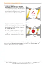
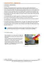
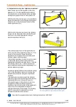
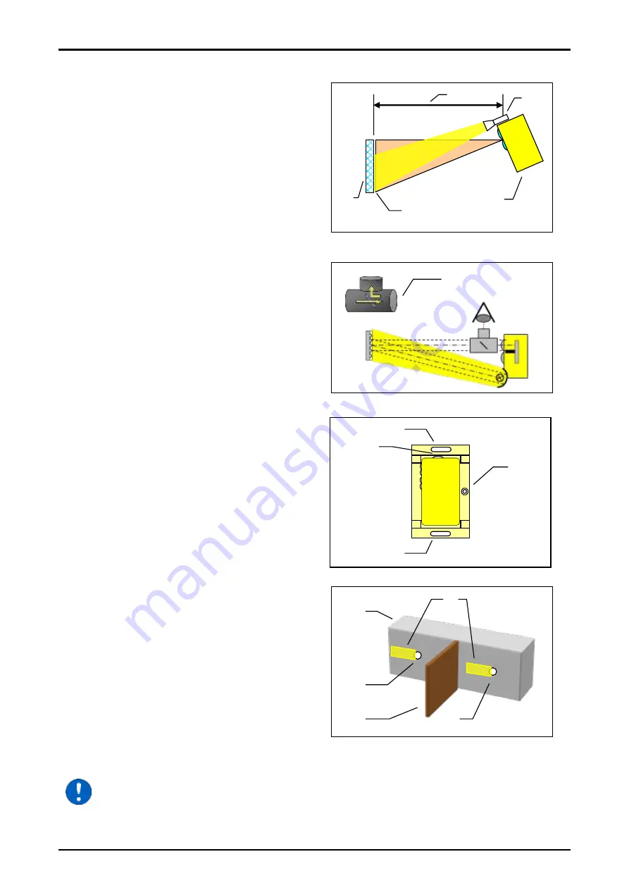
Adjustment using the “light beam method”
Both cranes are moved together to the limit
distance (
). For the adjustment the end of
the reflector (
) is illuminated with a portable
spotlight (
) placed close to the optical unit.
With the
lid of the device open,
it is possible to
detect the reflection of the brightly illuminated
reflector (
) on the transducer bench of the
reflex light barrier (
).
With the
lid of the device closed,
the reflector
image can be observed from outside through
the lens of the reflex light barrier using a
special adjustment help (
).
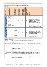
The vertical adjustment of the light barrier is
set by means of the adjusting screw (
). The
center of the reflector image should be
adjusted to the height of the transmitter and
receiver diode converter holes.
The slotted mounting (
and
) can be used
to rotate the device at the horizontal level.
Separately accessible spindle drives
– behind
the dummy screw (
)
– can be used to set
each individual optical system separately to a
definite distancing range.
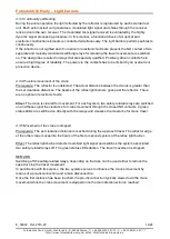
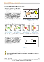
Graphical representation of the reflector image
(
) on the transducer bench (
) during the
adjustment procedure using the “light beam
method”.
The light barrier is able to sight the reflector
when the edge of the light image falls into the
transmitter hole (
) or receiver hole (
).
If the light images of the reflector move in a
straight line and horizontally across the
transducer bench during the further approach
travel, then the triangulation triangle is
clamped absolutely horizontally. The dividing
wall (
) prevents an optical short-circuit
between transmitter and receiver.
See also the separate document
„Setting Instructions CPV1038“
Fig.: 4.7-3
Fig.: 4.7-1
Fig.: 4.7-2
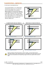
Fig.: 4.7-4: Representation of the reflector image
for a triangulation angle clamped to the right.

