


Users Manual Model 545™
Assembly Drawings
•
109
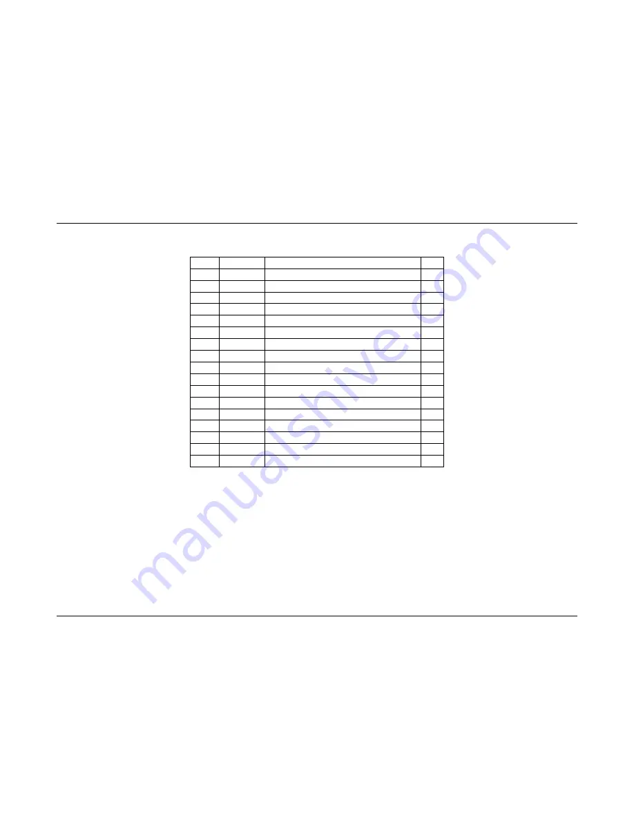
Feed Parts List
Item
Part #
Description
Qty
1
341206
Frame, Upright
1
2
351141
Ink Motor
1
3
344056K Drive Gear, 24T
1
4
990081
10-32 x ½ Cap Screw
6
5
990728
#10 Lock Washer
3
6
990017
6-32 x ½ Cap Screw
1
7
990037
#6 Washer SAE
1
8
991073
Standoff, 1 ¾, 10-32 THD
3
9
344051
Fixed Idler Shaft
1
10 374028
Pulley, 14T PBL FLG, 3/8 I.D.
1
11 990065
8-32 x 3/8 Button Head Screw
4
12 344053
Gear 156T, 3/8 O.D.
1
13 344052K Idler Shaft
1
14 244012
Pulley 14T SFL ¼ I.D.
1
15 344055
Belt, Timing 42T
1
16 354094
Roller Drive Assembly
1
17 989513
4mm “E”-Ring
1
Summary of Contents for 545
Page 2: ...This page intentionally blank ...
Page 78: ...76 Electrical Drawings Users Manual Model 545 Electrical Drawings Printer Wiring ...
Page 90: ......
Page 91: ...Users Manual Model 545 Assembly Drawings 89 Assembly Drawings ...
Page 94: ...92 Assembly Drawings Users Manual Model 545 Frame Assembly Drawing ...
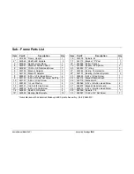
Page 96: ...94 Assembly Drawings Users Manual Model 545 Sub Frame Assembly Drawing ...
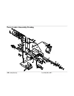
Page 98: ...96 Assembly Drawings Users Manual Model 545 Power Unwind Assembly Drawing ...
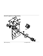
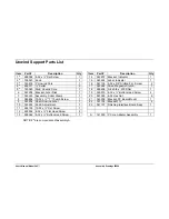
Page 100: ...98 Assembly Drawings Users Manual Model 545 Unwind Support Assembly Drawing ...
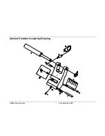
Page 104: ...102 Assembly Drawings Users Manual Model 545 Unwind Snubber Assembly Drawing ...
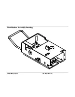
Page 106: ...104 Assembly Drawings Users Manual Model 545 Print Module Assembly Drawing ...
Page 108: ...106 Assembly Drawings Users Manual Model 545 Cartridge Support Deck Assembly Drawing ...
Page 110: ...108 Assembly Drawings Users Manual Model 545 Feed Assembly Drawing ...
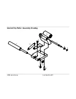
Page 114: ...112 Assembly Drawings Users Manual Model 545 Knife Assembly Drawing ...
Page 116: ...114 Assembly Drawings Users Manual Model 545 Stacker Assembly Drawing Part 1 ...
Page 118: ...116 Assembly Drawings Users Manual Model 545 Stacker Assembly Drawing Part 2 ...
Page 120: ...118 Assembly Drawings Users Manual Model 545 Rewind Assembly Drawing ...


