


34
•
Printer Operation / Adjustments
Users Manual Model 545™
Printer Setup
From time to time it may be necessary or desirable to reset the printer to a known
state of print / cut. The following procedure can be used to make the necessary
changes. Only adjust the adjustments that are needed in the order that follows;
1) Clean the machine as needed.
2) Check and adjust the unwind and web guides as needed for the fabric width that is
loaded on the machine.
3) Using a 5/64” hex key adjust station 1’s head swing arm stop screw to produce
print on the back of the label that has neither a gap or overlap in the center of the
print image. Rotating the screw counter clockwise will decrease the overlap or
increase the gap. Rotating it clockwise will decrease the gap or increase the
overlap. Once adjusted properly the image on the back of the label should appear
square with no gap or overlap in the center.
4) Adjust station 2’s head swing arm stop screw the same as station 1 to produce
print on the front of the label that has neither a gap or overlap in the center of the
print image.
5) Using the print line label format adjust the mount angle of the knife as needed to
produce a square cut. Loosen the two mount screws securing the knife module
and rotate the entire module then retighten the mount screws.
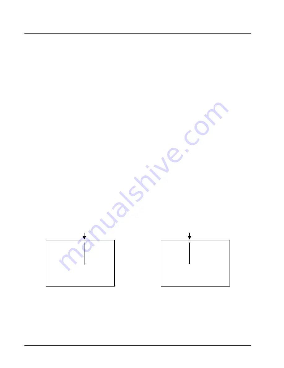
6) On the front panel adjust the PRINT POSITION STATION 1 to cause the inboard
half of the feed print line on the back of the label to be at 1.0”.
NOTE
: PRINT POSTION STATION 1 adjustment is opposite from all the other
adjustment. Using the module view a more negative number moves the
print to the right; a more positive number moves the print to the left.
-20
+20
7) On the front panel adjust the PRINT POSITION STATION 2 to cause the inboard
half of the feed print line on the front of the label to be at 1.0”.
Summary of Contents for 545
Page 2: ...This page intentionally blank ...
Page 78: ...76 Electrical Drawings Users Manual Model 545 Electrical Drawings Printer Wiring ...
Page 90: ......
Page 91: ...Users Manual Model 545 Assembly Drawings 89 Assembly Drawings ...
Page 94: ...92 Assembly Drawings Users Manual Model 545 Frame Assembly Drawing ...
Page 96: ...94 Assembly Drawings Users Manual Model 545 Sub Frame Assembly Drawing ...
Page 98: ...96 Assembly Drawings Users Manual Model 545 Power Unwind Assembly Drawing ...
Page 100: ...98 Assembly Drawings Users Manual Model 545 Unwind Support Assembly Drawing ...
Page 104: ...102 Assembly Drawings Users Manual Model 545 Unwind Snubber Assembly Drawing ...
Page 106: ...104 Assembly Drawings Users Manual Model 545 Print Module Assembly Drawing ...
Page 108: ...106 Assembly Drawings Users Manual Model 545 Cartridge Support Deck Assembly Drawing ...
Page 110: ...108 Assembly Drawings Users Manual Model 545 Feed Assembly Drawing ...
Page 114: ...112 Assembly Drawings Users Manual Model 545 Knife Assembly Drawing ...
Page 116: ...114 Assembly Drawings Users Manual Model 545 Stacker Assembly Drawing Part 1 ...
Page 118: ...116 Assembly Drawings Users Manual Model 545 Stacker Assembly Drawing Part 2 ...
Page 120: ...118 Assembly Drawings Users Manual Model 545 Rewind Assembly Drawing ...


