56
•
Maintenance
Users Manual Model 545™
Print Module Replacement / Height Adjustment
CAUTION: Turn off the power to the printer before removing or inserting the
print module(s).
DUE TO THE TOLERANCES IN THE PRINT MODULES AND OF THE
PRINT HEADS THEMSELVES, THE ENTIRE PRINT MODULE MUST
BE REPLACED - ONCE A PRINT HEAD HAS REACHED ITS END OF
LIFE.
1) Remove the ink cartridge from the printer in order to remove the print module.
2) Remove the print module by holding the release lever to the right and lifting the
print module from the printer using its handle.
3) Insert a replacement print module in the reverse order.
4) If the replacement print module does not function properly by swinging the print
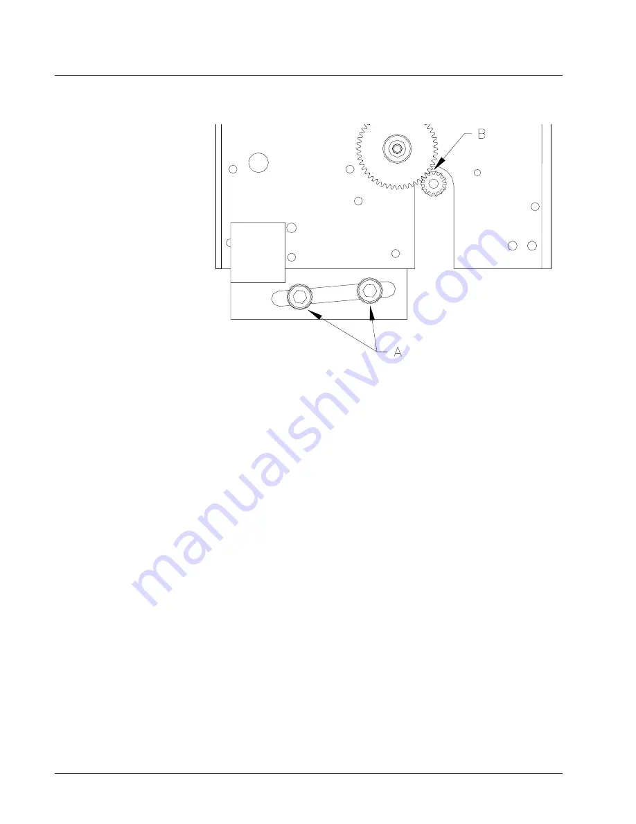
heads out to the print position, the module stop block may need to be adjusted.
These stop blocks are located beneath the print module under the front nose
cover of the machine. With the power off remove the cover by removing four
screws, two on either end of the cover then while holding the active unwind
pinch roller down slide the cover forward far enough to unplug the front panel
PCB. Once the PCB is unplugged - remove the cover and set aside. Adjust the
print module stop block as needed to cause the pinion gears (B) to fully mesh
without binding. This is achieved by loosening the two screws (A) securing the
stop block to the frame and then moving the stop block right or left to cause it to
raise or lower. Retighten the screws once the proper height is reached.
5) Replace the cover and perform the auto cleaning until the print heads are filled
with ink and printing a full image.
6) As a final test of the print module installation, run a test pattern to check the print
quality. You should observe an even grid of rectangles.
Summary of Contents for 545
Page 2: ...This page intentionally blank ...
Page 78: ...76 Electrical Drawings Users Manual Model 545 Electrical Drawings Printer Wiring ...
Page 90: ......
Page 91: ...Users Manual Model 545 Assembly Drawings 89 Assembly Drawings ...
Page 94: ...92 Assembly Drawings Users Manual Model 545 Frame Assembly Drawing ...
Page 96: ...94 Assembly Drawings Users Manual Model 545 Sub Frame Assembly Drawing ...
Page 98: ...96 Assembly Drawings Users Manual Model 545 Power Unwind Assembly Drawing ...
Page 100: ...98 Assembly Drawings Users Manual Model 545 Unwind Support Assembly Drawing ...
Page 104: ...102 Assembly Drawings Users Manual Model 545 Unwind Snubber Assembly Drawing ...
Page 106: ...104 Assembly Drawings Users Manual Model 545 Print Module Assembly Drawing ...
Page 108: ...106 Assembly Drawings Users Manual Model 545 Cartridge Support Deck Assembly Drawing ...
Page 110: ...108 Assembly Drawings Users Manual Model 545 Feed Assembly Drawing ...
Page 114: ...112 Assembly Drawings Users Manual Model 545 Knife Assembly Drawing ...
Page 116: ...114 Assembly Drawings Users Manual Model 545 Stacker Assembly Drawing Part 1 ...
Page 118: ...116 Assembly Drawings Users Manual Model 545 Stacker Assembly Drawing Part 2 ...
Page 120: ...118 Assembly Drawings Users Manual Model 545 Rewind Assembly Drawing ...