


Users Manual Model 545™
Maintenance
•
61
General Machine Cleaning
The machine should be cleaned every eight hours of use or as needed. With the
exception of the print heads and the optical sensors, the machine can be cleaned
using an alcohol base solution. Simply apply a liberal amount of alcohol to a clean
rag and wipe down the machine components starting at the unwind and ending at the
stacker.
Printheads
Refer to the Automated Print Head and Manual Manifold Cleaning sections for
cleaning the print heads.
NOTE:
The print head
guards
can be cleaning with alcohol.
Optical Sensors
When an erroneous interlock condition occurs or print registration in reference to a
sense mark becomes inconsistent or erratic - a sensor may need to be cleaned.
Always use clean supplies when cleaning sensors. Never use anything abrasive on
any of the sensors. Never use an alcohol based solution on any of the sensors. Dry
air or a foam swab are the recommended supplies to use when cleaning a sensor.
Either blow the dust / debris from the sensor using dry clean compressed air or wipe
the sensor with a dry clean swab.
Knife Adjustment
The knife has an adjustment to square the cut to the fabric. To make
the adjustment, loosen the two cap screws, one on top of the knife and
one below the knife, using the 3/16” ball driver. Move the knife in
the direction desired to square the cut and retighten.
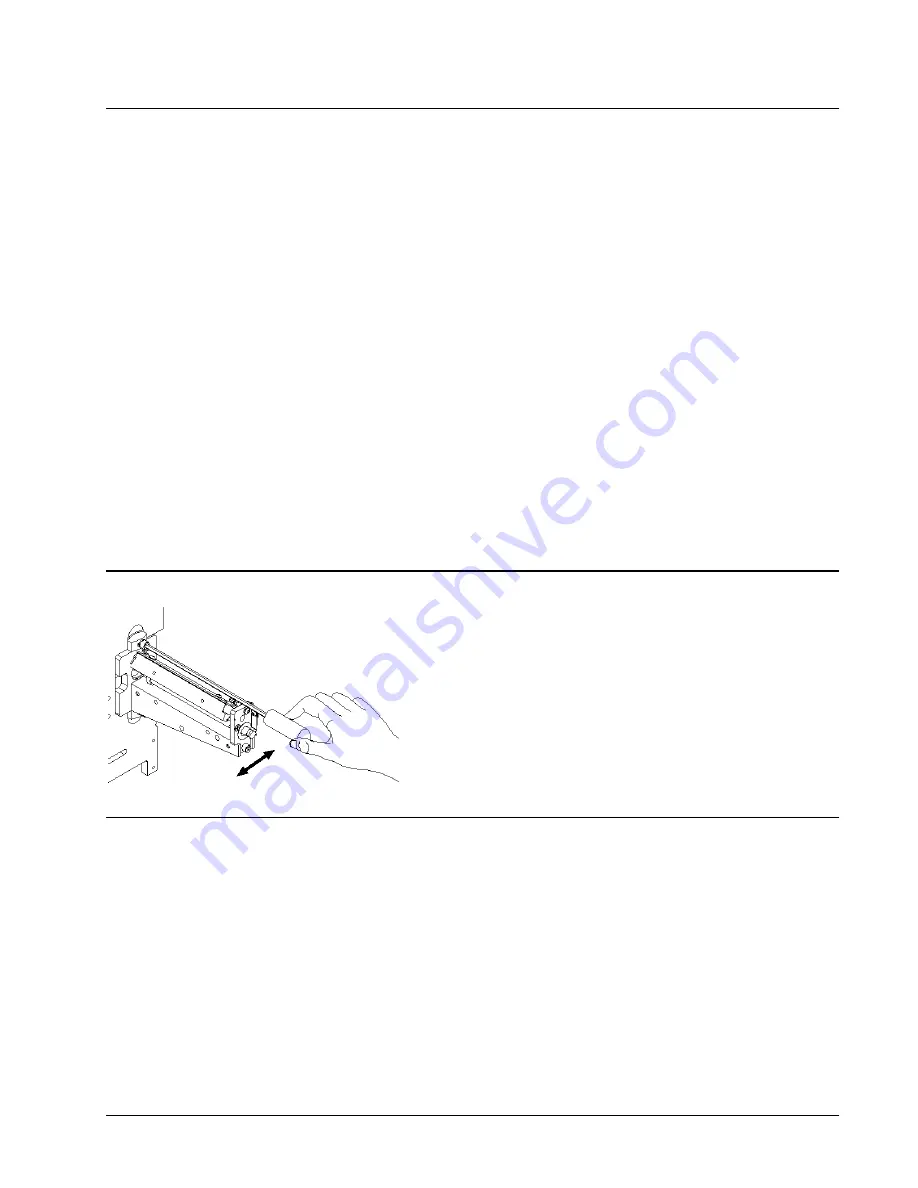
Feed Open Interlock Switch Adjustment
With the machine rear cover removed - while turning the feed lever knob back and
forth you should heard the switch clicking. If not, the switch bale is adjusted by
carefully bending it as needed.
Summary of Contents for 545
Page 2: ...This page intentionally blank ...
Page 78: ...76 Electrical Drawings Users Manual Model 545 Electrical Drawings Printer Wiring ...
Page 90: ......
Page 91: ...Users Manual Model 545 Assembly Drawings 89 Assembly Drawings ...
Page 94: ...92 Assembly Drawings Users Manual Model 545 Frame Assembly Drawing ...
Page 96: ...94 Assembly Drawings Users Manual Model 545 Sub Frame Assembly Drawing ...
Page 98: ...96 Assembly Drawings Users Manual Model 545 Power Unwind Assembly Drawing ...
Page 100: ...98 Assembly Drawings Users Manual Model 545 Unwind Support Assembly Drawing ...
Page 104: ...102 Assembly Drawings Users Manual Model 545 Unwind Snubber Assembly Drawing ...
Page 106: ...104 Assembly Drawings Users Manual Model 545 Print Module Assembly Drawing ...
Page 108: ...106 Assembly Drawings Users Manual Model 545 Cartridge Support Deck Assembly Drawing ...
Page 110: ...108 Assembly Drawings Users Manual Model 545 Feed Assembly Drawing ...
Page 114: ...112 Assembly Drawings Users Manual Model 545 Knife Assembly Drawing ...
Page 116: ...114 Assembly Drawings Users Manual Model 545 Stacker Assembly Drawing Part 1 ...
Page 118: ...116 Assembly Drawings Users Manual Model 545 Stacker Assembly Drawing Part 2 ...
Page 120: ...118 Assembly Drawings Users Manual Model 545 Rewind Assembly Drawing ...


