


64
•
Maintenance
Users Manual Model 545™
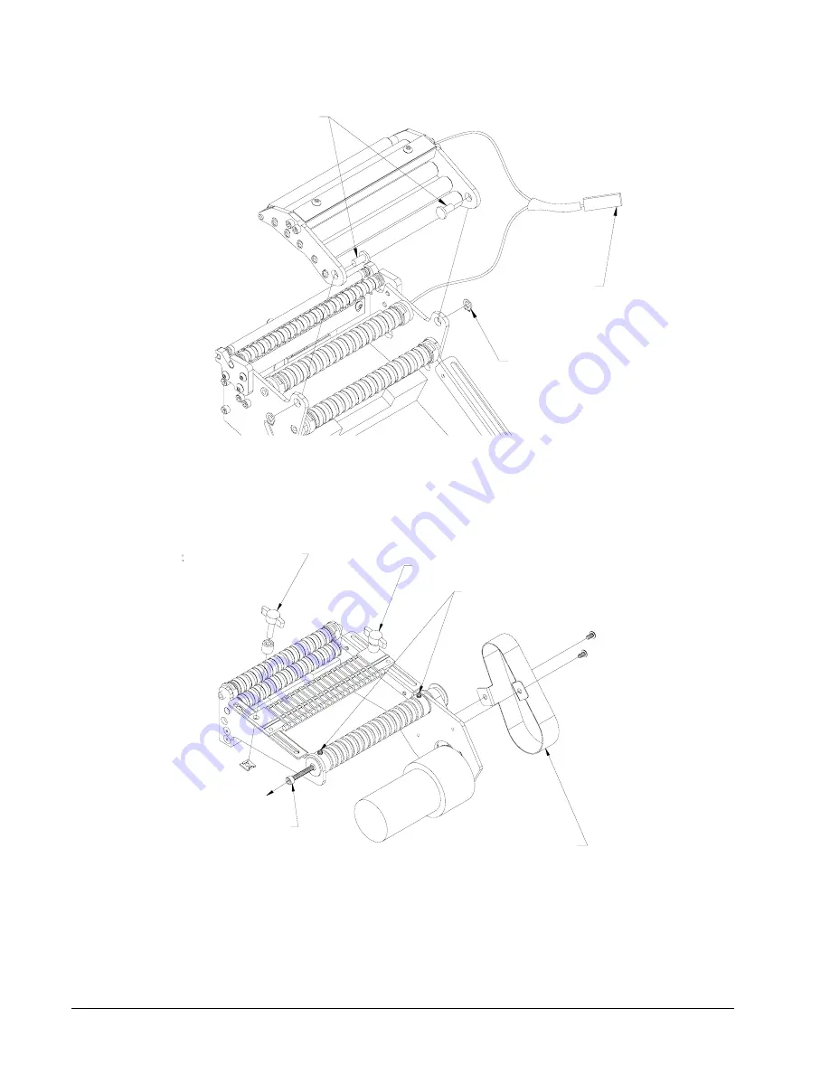
JAM SENSOR
HARNESS
RIVETS
SNAP RING
FIGURE 2
2. Remove upper conveyor roller assembly by removing jam sensor harness
connector, snap-rings and rivets.
8-32 SCREW
(SEE ITEM 5)
DRIVE BELT
COVER
6-32 SET SCREWS
REMOVE
LOOSEN
FIGURE 3
3. Remove the drive belt cover.
4. Loosen 6-32 set screws in ends of main drive roller. (See figure 3)
Summary of Contents for 545
Page 2: ...This page intentionally blank ...
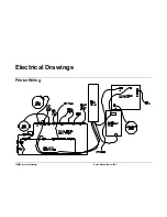
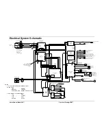
Page 78: ...76 Electrical Drawings Users Manual Model 545 Electrical Drawings Printer Wiring ...
Page 90: ......
Page 91: ...Users Manual Model 545 Assembly Drawings 89 Assembly Drawings ...
Page 94: ...92 Assembly Drawings Users Manual Model 545 Frame Assembly Drawing ...
Page 96: ...94 Assembly Drawings Users Manual Model 545 Sub Frame Assembly Drawing ...
Page 98: ...96 Assembly Drawings Users Manual Model 545 Power Unwind Assembly Drawing ...
Page 100: ...98 Assembly Drawings Users Manual Model 545 Unwind Support Assembly Drawing ...
Page 104: ...102 Assembly Drawings Users Manual Model 545 Unwind Snubber Assembly Drawing ...
Page 106: ...104 Assembly Drawings Users Manual Model 545 Print Module Assembly Drawing ...
Page 108: ...106 Assembly Drawings Users Manual Model 545 Cartridge Support Deck Assembly Drawing ...
Page 110: ...108 Assembly Drawings Users Manual Model 545 Feed Assembly Drawing ...
Page 114: ...112 Assembly Drawings Users Manual Model 545 Knife Assembly Drawing ...
Page 116: ...114 Assembly Drawings Users Manual Model 545 Stacker Assembly Drawing Part 1 ...
Page 118: ...116 Assembly Drawings Users Manual Model 545 Stacker Assembly Drawing Part 2 ...
Page 120: ...118 Assembly Drawings Users Manual Model 545 Rewind Assembly Drawing ...


