background image

P/N: 4809654 v5.0 

©2010 Paxton Automotive 

All Rights Reserved, Intl. Copr. Secured 

24

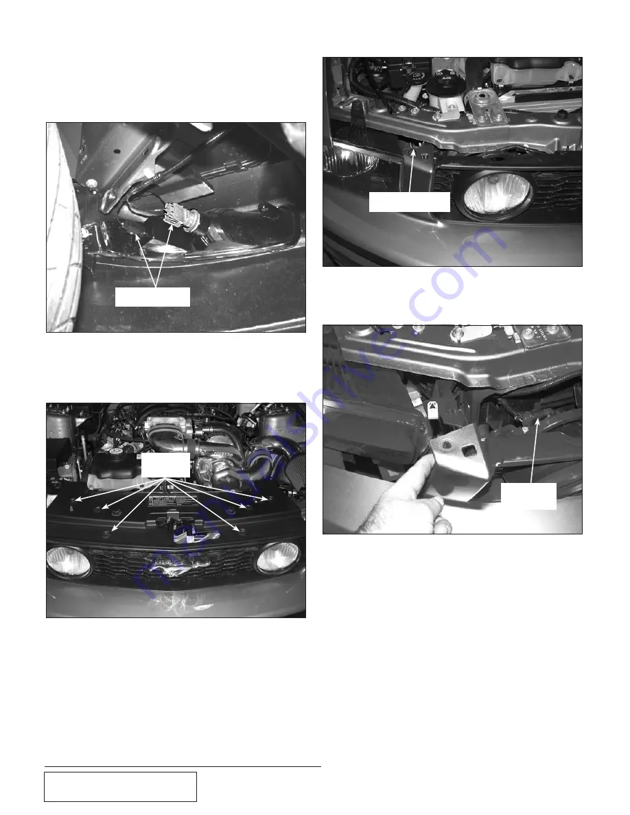
6.

  Disconnect the connectors on the parking 

and the lower fog lights.  (See 

Fig. 8A-e

.)

7.

  Remove the six nylon clips retaining the 

upper radiator core support cover.  (See 

Fig. 8A-f

.)

8.

  Remove the two 10mm headed bolts (1 

each side upper portion of grill).  (See 

Fig. 

8A-g

.)

Fig. 8A-e

Fig. 8A-g

Fig. 8A-f

NYLON 

CLIPS

10mm HEADED 

BOLT

LIGHT 

CONNECTIONS

8A.  BUMPER CovER & SPLASH PAN 

REMovAL

 (H.o. kits only),  cont’d

10.

  Pull out on the bumper cover

11.

  Remove the connectors to the driving 

lights in the grill.  (See 

Fig. 8A-h

.)

12.

  Remove the bumper cover and set aside.  

(See 

Fig. 8A-i

.)  

13

.  

(2010 Models only)

  Remove air diversion 

panels on both sides of the radiator by 

removing nylon push pins. Set them aside 

for trimming in a future step. (See Fig. 

8A-j).

9.

  Lift up on the tabs releasing them from the 

clips.  (See 

Fig. 8A-h

.)

Fig. 8A-h

DRIVING 

LIGHT 

CONNECTOR

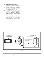
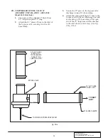
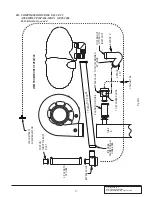
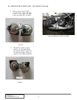
Summary of Contents for Novi

Page 1: ...tion Guide for the Paxton Automotive Novi Supercharger for the 2005 2010 Mustang GT Paxton Automotive 1300 Beacon Place Oxnard CA 93033 805 487 3796 FAX 805 247 0669 PaxFreehandBW Lg 2 eps 10 04 04 Legal in California only for racing vehicles which may never be used upon a highway 2007 2010 models ...

Page 2: ... any clutch transmission drive line or engine dam age Exclusions from Paxton warranty coverage considerations include but not lim ited to 1 Neglect abuse lack of maintenance abnormal operation or improper installation 2 Continued operation with an impaired vehicle or sub system 3 The combined use of Paxton components with other modifications such as but not limited to exhaust headers aftermarket c...

Page 3: ...3 8A BUMPER COVER AND SPLASH PAN H O Kits Only 23 8B CHARGE AIR COOLER CORE 2005 2006 Model H O Kits Only 26 8C COMPRESSOR BYPASS VALVE 1 ASSEMBLY INSTALLATION 2005 2006 Model H O Kits Only 28 8D COMPRESSOR BYPASS VALVE 2 ASSEMBLY INSTALLATION 2005 2006 Model H O Kits Only 29 8E HORN BRACKET RELOCATION 2010 Model H O Kits Only 32 8F AIR DIVERSION PANEL MODIFICATION 2010 Model H O kits only 33 8G C...

Page 4: ...ons geome try and engineering features shown in this product are the exclusive prop erty of Paxton Automotive This product may not be copied or duplicated in whole or part abstractly or fundamentally intentionally or fortuitously nor shall any design dimension or other information be incorporated into any product or apparatus without prior written consent of Paxton Automotive 2005 2010 Mustang GT ...

Page 5: ... your vehicle Thereafter always use a high grade SF rated engine oil or a high quality synthetic and change the oil and fil ter every 3 000 miles or less Never attempt to extend the oil change interval beyond 3 000 miles regardless of oil manufactur er s claims as potential damage to the supercharger may result 6 Before beginning installation replace all spark plugs that are older than 1 year or 2...

Page 6: ...YLON 4 8PN201 050 CAC ASY 05 GT AIR AIR 1 8PN101 050 WELDED CORE ASY 05 MUST GT 1 4PFU012 021 DISCH DUCT T B 05 MUSTANG 1 4PFU012 030 CAC TUBE A 05 MUST GT 1 4PFU012 040 CAC TUBE B 05 MUST GT 1 4PFU012 050 CAC TUBE C 05 MUST GT 1 4PFU012 060 CAC TUBE D 05 MUST GT 1 4PFU012 070 CAC TUBE E 05 MUST GT 1 7PS300 301 BUMP HOSE Ø3 00 x 3 00 L 3 7PS300 300 SLEEVE BLACK Ø3 00 x 3 00 L 2 7R002 048 48 SAE TY...

Page 7: ...MP 1 7R004 006 STEPLESS CLAMP 11 3 x 5mm WIDE 4 5W001 022 T TAP CONN 14 16 AWG 2 5W001 009 16 14GA MALE SLIDE INSULATED 2 5W001 080 FUSE 20AMP MINI BLADE 1 7P375 099 Y UNION 3 8 BARBED TEFLON 1 7U032 025 HOSE 5 16 ID 3 8 OD 1 32 W 6 25 7U032 030 HOSE SPIRAL 3 8 CUFF ID 1 L 2 2005 2006 Mustang GT H O Part No 1001850 cont d PaxFreehandBW Lg 2 eps 10 04 04 Part No Description Qty IMPORTANT Before beg...

Page 8: ...C080 140 8mm x 1 25 x 140 BOLT 2 4PCS016 160 PULLEY 3 5 1 2A046 120 BELT GATES K061203 1 4FU214 021 COOLANT BYPASS HOSE RELOC ASY 05 GT 1 4FU114 021 WATER OUTLET ASY 05 MUS GT 1 7J875 010 7 8 SEALING WASHER 1 7F875 010 NUT 7 8 14 SHORT JAM 1 7U133 050 1 5 x 90 HOSE LONG LEG 1 7U133 190 HOSE COOLANT DRIV S SIDE 05 MUS 1 7U038 000 3 4 HEATER HOSE 3 5 7P375 075 3 4 HOSE BARB UNION BRASS 1 7ROO2 020 2...

Page 9: ...RE PURPLE 1 5W0011 007 3 16 HEAT SHRINK TUBING 1 5 5W0011 005 3 8 PLASTIC WIRE LOOM 1 5 5W001 012 18 22GA BUTT CONN RED INSUL 12 7U033 020 HOSE 5 8 ID CLASS 1 EMISSIONS 6 4PFU112 010 AIR INLET ASY 05 MUS GT 1 4FU012 010 INLET DUCT A 05 MUS GT 1 4FU012 015 INLET DUCT B 05 MUS GT 1 7R002 056 56 SAE TYPE F SS HOSE CLAMP 1 7PS400 200 SLEEVE BLACK 4 0 OD x 2 L 3 7PS400 351 SLEEVE 4 0 x 3 5 x 2 35 L 1 7...

Page 10: ...56 082 5 32 TEE 2 7U030 046 5 32 VACUUM LINE 8 8D001 001 STD COMPRESS BYPASS VALVE 2 7U034 016 1 GS HEATER HOSE 2 5 7P750 100 3 4 NPT x 1 HOSE FITTING 1 7P218 156 VAC TEE 7 32 7 32 5 32 1 7U100 055 TIE WRAP 7 5 NYLON 4 7R002 040 40 SAE TYPE F SS HOSE CLAMP 1 7U133 045 RUBBER ELBOW Ø1 x 45 1 7PS300 275 REDUCER BLK Ø3 TO 2 75 1 7PS300 045 ELBOW BLK SIL Ø3 x 45 1 PaxFreehandBW Lg 2 eps 10 04 04 Part ...

Page 11: ...MOD ASY 05 MUS GT 1 7P375 106 PCV VALVE FORD 3 8 HOSE 1 7P625 375 REDUCER 5 8 BARB TO 3 8 BARB 1 7R001 006 6 STNLS HOSE CLAMP NARROW 2 7R001 008 8 STNLS HOSE CLAMP 3 7R002 010 10 SAE TYPE F SS HOSE CLAMP 1 7U032 016 3 8 EFI FUEL HSE HI PSR 5 5W018 030 18GA STRD WIRE GREY 1 5W018 010 18GA STRD WIRE RED 1 5W018 020 18GA STRD WIRE BLK UL1015 1 5W018 080 18GA STRD WIRE BLUE BULK 1 5W018 090 18GA STRD ...

Page 12: ...MUST GT 1 4PFU012 050 CAC TUBE C 05 MUST GT 1 4PFU012 060 CAC TUBE D 05 MUST GT 1 4PFU012 070 CAC TUBE E 05 MUST GT 1 7PS300 301 BUMP HOSE Ø3 00 x 3 00 L 3 7PS300 300 SLEEVE BLACK Ø3 00 x 3 00 L 2 7R002 048 48 SAE TYPE F SS HOSE CLAMP 14 7R002 072 72 SAE TYPE F SS HOSE CLAMP 2 7S300 003 RUBBER ELBOW 3 MODIFIED 2 7PS450 200 SLEEVE BLACK Ø4 5 x 2 0 L 1 2A017 036 SPACER PLTBRGHSG 0186 4 7C080 035 M8 ...

Page 13: ...P 1 7R004 006 STEPLESS CLAMP 11 3 x 5mm WIDE 4 5W001 022 T TAP CONN 14 16 AWG 2 5W001 009 16 14GA MALE SLIDE INSULATED 2 5W001 080 FUSE 20AMP MINI BLADE 1 7P375 099 Y UNION 3 8 BARBED TEFLON 1 7U032 025 HOSE 5 16 ID 3 8 OD 1 32 W 6 25 7U032 030 HOSE SPIRAL 3 8 CUFF ID 1 L 2 2005 2006 Mustang GT H O Part No 1001850SL cont d PaxFreehandBW Lg 2 eps 10 04 04 Part No Description Qty IMPORTANT Before be...

Page 14: ...ER OUTLET ASY 05 MUS GT 1 7J875 010 7 8 SEALING WASHER 1 7F875 010 NUT 7 8 14 SHORT JAM 1 7U133 050 1 5 x 90 HOSE LONG LEG 1 7U133 190 HOSE COOLANT DRIV S SIDE 05 MUS 1 7U038 000 3 4 HEATER HOSE 3 5 7P375 075 3 4 HOSE BARB UNION BRASS 1 7ROO2 020 20 SAE TYPE F SS HOSE CLAMP 4 7ROO2 024 24 SAE TYPE F SS HOSE CLAMP 2 7P125 002 FREEZE PLUG Ø1 25 25 TAL 1 7R002 010 10 SAE TYPE F SS HOSE CLAMP 4 7P125 ...

Page 15: ...ASS 1 EMISSIONS 6 4PFU112 010 AIR INLET ASY 05 MUS GT 1 4FU012 010 INLET DUCT A 05 MUS GT 1 4FU012 015 INLET DUCT B 05 MUS GT 1 7R002 056 56 SAE TYPE F SS HOSE CLAMP 1 7PS400 200 SLEEVE BLACK 4 0 OD x 2 L 3 7PS400 351 SLEEVE 4 0 x 3 5 x 2 35 L 1 7R002 064 64 SAE TYPE F SS HOSE CLAMP 6 8H040 235 AIR FILTER 4 0 FLG x 7 0 L 1 8A003 071 MAF 3 8 ID 05 MUS GT 1 7P750 102 3 4 NPT x 1 x 90 HOSE FIT 1 7P25...

Page 16: ...ESS BYPASS VALVE 2 7U034 016 1 GS HEATER HOSE 2 5 7P750 100 3 4 NPT x 1 HOSE FITTING 1 7P218 156 VAC TEE 7 32 7 32 5 32 1 7U100 055 TIE WRAP 7 5 NYLON 4 7R002 040 40 SAE TYPE F SS HOSE CLAMP 1 7U133 045 RUBBER ELBOW Ø1 x 45 1 7PS300 275 REDUCER BLK Ø3 TO 2 75 1 7PS300 045 ELBOW BLK SIL Ø3 x 45 1 2007 2008 Mustang GT H O SL Part No 1001852SL cont d PARTS LIST PaxFreehandBW Lg 2 eps 10 04 04 Part No...

Page 17: ... 2 7R001 008 8 STNLS HOSE CLAMP 3 7R002 010 10 SAE TYPE F SS HOSE CLAMP 1 7U032 016 3 8 EFI FUEL HSE HI PSR 5 5W018 030 18GA STRD WIRE GREY 1 5W018 010 18GA STRD WIRE RED 1 5W018 020 18GA STRD WIRE BLK UL1015 1 5W018 080 18GA STRD WIRE BLUE BULK 1 5W018 090 18GA STRD WIRE BROWN BULK 1 5W018 100 18GA STRD WIRE PURPLE 1 5W001 007 3 16 HEAT SHRINK TUBING 1 5 5W001 005 3 8 PLASTIC WIRE LOOM 1 5 5W001 ...

Page 18: ... RED INSUL 12 7U033 020 HOSE 5 8 ID CLASS 1 EMISSIONS 6 4PFU112 010 AIR INLET ASY 05 MUS GT 1 4FU012 010 INLET DUCT A 05 MUS GT 1 4FU012 015 INLET DUCT B 05 MUS GT 1 7R002 056 56 SAE TYPE F SS HOSE CLAMP 1 7PS400 200 SLEEVE BLACK 4 0 OD x 2 L 3 7PS400 351 SLEEVE 4 0 x 3 5 x 2 35 L 1 7R002 064 64 SAE TYPE F SS HOSE CLAMP 6 8H040 235 AIR FILTER 4 0 FLG x 7 0 L 1 8A003 071 MAF 3 8 ID 05 MUS GT 1 7P75...

Page 19: ... 5 32 VACUUM LINE 8 8D001 001 STD COMPRESS BYPASS VALVE 2 7U034 016 1 GS HEATER HOSE 2 5 7P750 100 3 4 NPT x 1 HOSE FITTING 1 7P218 156 VAC TEE 7 32 7 32 5 32 1 7U100 055 TIE WRAP 7 5 NYLON 4 7R002 040 40 SAE TYPE F SS HOSE CLAMP 1 7U133 045 RUBBER ELBOW Ø1 x 45 1 7PS300 275 REDUCER BLK Ø3 TO 2 75 1 7PS300 045 ELBOW BLK SIL Ø3 x 45 1 PaxFreehandBW Lg 2 eps 10 04 04 IMPORTANT Before beginning insta...

Page 20: ...P N 4809654 v5 0 2010 Paxton Automotive All Rights Reserved Intl Copr Secured xx This Page Left Intentionally Blank ...

Page 21: ...plastic tube is to apply a small amount of heat to the tube and slide the connector free B Disconnect the mass air flow MAF sensor plug and remove the inlet duct and upper air fil ter cover from the car See Figs 1 a 1 b 1 c 1 PREPARATION REMOVAL Fig 1 b Fig 1 c MAF CONNECTOR RETAIN THIS END Fig 1 a CRANKCASE BREATHER HOSE RETAIN THIS END Fig 1 d 10mm HEADED BOLT THROTTLE BODY CLAMP Fig 1 e NYLON C...

Page 22: ...e the thermostat housing from the large formed hose leading to the engine block and the lower outlet of the radiator See Fig 1 h Set the thermostat housing aside to be reinstalled in a later step K 2005 2006 Only Remove the lower hose on the radiator and set the hose aside as it will not be reused L Drain and remove the power steering reservoir This reservoir will be relocated in a later step M Di...

Page 23: ...lled in a later step See Figs 1 i 1 j 4 Locate and remove the remaining 10mm headed bolts retaining the intake manifold to the cylinder heads There are five on each side 5 2005 2006 Only Remove the intake manifold and set aside so it can be rein stalled after modifications to the coolant crossover tube are made 6 2007 2010 Only It is not necessary to remove the intake manifold from the vehi cle co...

Page 24: ...r Remove the wiring harness from the retaining clips that hold it to the valve cover Move the harness out of the way This harness will have to be relocated to gain clearance for the super charger Fig 1 k STUD BOLT MODIFY STUD REMOVE 13mm HEADED BOLT REMOVE STUD BOLT R There is a small tab that secures the wiring har ness in place on the valve cover that will need to be removed to gain clearance fo...

Page 25: ...s steel 4 hose to the 4 fit ting installed in the street TEE See Fig 2 a E Route the hose away from hot sharp or moving parts and to the top of the engine to be attached to the supercharger oil feed NOTE The oil feed hose to the S C will be installed in a later step of the installation Temporarily cap the open end of the hose to prevent contamination to the inside of the hose F Reinstall the facto...

Page 26: ...P N 4809654 v5 0 2010 Paxton Automotive All Rights Reserved Intl Copr Secured 6 This Page Left Intentionally Blank ...

Page 27: ...e forward 3 4 from the first bolt on the side of the oil pan See Fig 3 a 3 OIL DRAIN ASSEMBLY INSTALLATION Fig 3 b Fig 3 a 3 4 5 8 F Thoroughly clean the threaded area Apply a small amount of silicone sealer or teflon paste to the new threads Apply more sealer to the 3 8 NPT hose fitting and secure in the hole Make sure a seal is formed all around the fit ting See Fig 3 b G Drain the engine oil an...

Page 28: ...P N 4809654 v5 0 2010 Paxton Automotive All Rights Reserved Intl Copr Secured 8 This Page Left Intentionally Blank ...

Page 29: ... 4 1 b F Attach the hoses from the reservoir to the facto ry P S hoses and secure with the supplied clamps Trim for best fit Secure the hose to the fan shroud away from heat and moving objects G It will be necessary to trim the corner of the radiator core support cover to clear the relocat ed P S reservoir See Fig 4 1 d D Attach the 3 4 and the 3 8 hose barb unions to the factory hoses using the f...

Page 30: ...stall PS reservoir assembly in loca toin shown Route hoses toward the front of the vehicle away from exhaust and moving objects G Connect previously installed PS hoses from reservoir the the factory PS hoses using the appropriate unions and hose clamps D Using a 3 4 brass union and two stepless clamps attach the 90 bend to a length of sup plies 3 4 hose as shown Do the same to the 3 8 hose See Fig...

Page 31: ...emove the two remaining 10mm head bolts securing the cross over tube to the cylinder heads F Remove the factory O ring type gaskets to pre vent damage Clamp the driver s side steel hose barb end of the coolant cross over tube in a vise as shown Using a small amount of heat heat the aluminum cross over tube Using a twisting motion remove the steel insert See Fig 5 1 d Penetrating oil will also aid ...

Page 32: ...jam nut all the way onto the fitting Tighten the fitting in the position shown See Fig 5 1 h Secure with the jam nut NOTE It is recommended that sealant be used to seal the thread of the fitting K Reinstall the factory O ring gaskets to the crossover tube L Set the coolant crossover tube back in its origi nal location M Reinstall the two 10mm headed bolts through the cross over tube into the cylin...

Page 33: ...ers and tighten to factory specifications Tighten the two 10mm headed bracket bolts that were previously left loose T Reconnect the IMRC control unit at the rear of the manifold along with the vacuum hose U Remove the small clips that retain the factory fuel injectors to the fuel rail Remove the facto ry fuel injectors and set a side these will not be reused V Locate the supplied fuel injectors Lu...

Page 34: ...head surface is clean E Lower the intake manifold onto the cylinder heads F Install the ten factory 10mm headed manifold retainers and tighten to factory specifications G Remove the small clips that retain the factory fuel injectors to the fuel rail Remove the fac tory fuel injectors and set aside These will not be reused H Locate the supplied fuel injectors Lubricate the injector O rings with cle...

Page 35: ...eviously and two 24 hose clamps provided install the short end of the 90 stainless tube 4FU014 060 onto the repositioned thermo stat housing See Fig 5 2 n O Install the remainder of the factory radiator hose using one factory hose clamp and one 24 hose clamp See Fig 5 2 o 5 2 THERMOSTAT HOUSING RADIATOR HOSE MODIFICATION 2007 2010 Model Year Only cont d Fig 5 2 l END CONNECTED TO RADIATOR CUT APPR...

Page 36: ...P N 4809654 v5 0 2010 Paxton Automotive All Rights Reserved Intl Copr Secured 16 This Page Left Intentionally Blank ...

Page 37: ...OLT SPACERS INSTALLED 2005 2008 NON COOLED AND 2010 H O MODEL IDLER LOCATION 3 8 16 x 3 75 SCREW A The mounting plate is provided with the spacers and bolts as they would be installed on the vehicle Keep these bolts and spacers marked as to their locations They are all different in size and mismatching them will result is misalign ment of the mounting plate B Locate the two supplied stud bolt spac...

Page 38: ...Secured 18 Fig 6 e Belt routing A C COMPRESSOR PULLEY FACTORY TENSIONER PULLEY ALTERNATOR PULLEY SUPPLIED IDLER PULLEY 4PCS016 160 FACTORY POWER STEERING PULLEY CRANK SHAFT PULLEY FACTORY IDLER PULLEYS SUPERCHARGER PULLEY 6 SUPERCHARGER MOUNTING PLATE INSTALLATION cont d ...

Page 39: ...pplied 1 8 NPT x 4 straight fitting from assembly 4FU130 026 to the oil feed fit ting on the supercharger NOTE Use only clean engine oil on the pipe threads Teflon tape or pipe sealant is not recommended as if might loosen and cause blockage of the small oil feed orifice resulting in possible supercharger failure O Attach the supercharger assembly to the mount ing plate using the previously instal...

Page 40: ...P N 4809654 v5 0 2010 Paxton Automotive All Rights Reserved Intl Copr Secured 20 This Page Left Intentionally Blank ...

Page 41: ...he 13 end NOTE Because of manufacturing tolerances it is best to leave this hose long and trim to fit E Install the long end of the modified hose to the outlet of the radiator with a 24 hose clamp Leave the clamp loose for adjustment F Install the thermostat housing to the open end of the new the lower radiator hose and the large formed factory hose Adjust the thermostat s location making sure it ...

Page 42: ...e thermostat housing I Install the opposite end to the previouusly modified coolant cross over tube Secure using the 20 hose clamps provided See Fig 7 c 7 THERMOSTAT HOUSING RELOCATION 2005 2006 Only cont d NOTE The hose clamps will be left loose for adjustment of the thermostat s location until after the installation of the supercharger and supercharger mounting bracket are installed ...

Page 43: ...aining the lower splash panel See Fig 8A a 3 Remove the six Phillips head screws 3 each side on the lower portions of the plastic inner fender liners See Fig 8A b 4 Remove the five plastic clips retaining the front portion of the fender liner Both sides need to be removed See Fig 8A c 5 Remove the four 10mm nuts 2 each side retaining the bumper cover to the fenders See Fig 8A d Fig 8A a Fig 8A b F...

Page 44: ...e Fig 8A g Fig 8A f NYLON CLIPS 10mm HEADED BOLT LIGHT CONNECTIONS 8A BUMPER COVER SPLASH PAN REMOVAL H O Kits Only cont d 10 Pull out on the bumper cover 11 Remove the connectors to the driving lights in the grill See Fig 8A h 12 Remove the bumper cover and set aside See Fig 8A i 13 2010 Models Only Remove air diversion panels on both sides of the radiator by removing nylon push pins Set them asi...

Page 45: ...e metal bumper support See Fig 8A k 14 Remove four nylon push pins from the styrofoam bumper support and set the support and the pins aside to be rein stalled See Fig 8A j Fig 8A l SPACERS PROVIDED 18 Replace the styrofoam bumper support using the factory retainers AIR DIVERSION PANELS 16 Replace the bolts previously removed with the four 8mm 1 25 x 35mm long bolts and washers provided 17 Install ...

Page 46: ... radiator closer to the frame See Fig 8B d 8B CHARGE AIR COOLER CORE INSTALLATION 2005 2006 Model H O Kits Only Fig 8B c Fig 8B d SHORT ENDS OF 90 ELBOWS PROVIDED FITTING ROTATED TOWARD FRONT OF VEHICLE NOTE Use Fig 8B a to aid in the next few steps 1 Locate the Charge Air Cooler assembly Place the cooler onto the previously installed hardware making sure the four spacers remain in place Align the...

Page 47: ...sting for best fit and clearance 8 Install the short end of tube D into the open end of the passenger s side 90 rubber elbow previously install See Fig 8B f 9 Attach a 3 x 3 sleeve and 48 hose clamps to the open end of tube D 10 Install the short end of tube E into the sleeve attached to tube D Secure the tube support bracket using the previously installed 48 hose clamp See Fig 8B g NOTE For bette...

Page 48: ...r 90 elbow and cut approximately 6 from the long end and 1 from the short end Attach the long end to the by pass valve discharge and secure using the 16 hose clamps provided See Fig 8C a 8D c 3 Attach the open end of the 3 long hose to the by pass port on tube A and secure using a 16 hose clamp The open end of the 90 hose will be connected to the inlet duct in a later step See Fig 8D c Fig 8C a TR...

Page 49: ... pass valve securing it with a 16 hose clamp 4 5 x Ø1 HOSE TRIM TO FIT TO DISCHARGE TUBE AT THE THROTTLE BODY 15 x Ø1 HOSE TRIM TO FIT TO MANIFOLD PRESSURE VACUUM 16 HOSE CLAMPS TO INLET DUCT BYPASS VALVE 3 Secure the 15 piece to the by pass valve discharge using a 16 hose clamp 4 Attach the open end of the 4 5 hose to the by pass port on the cast discharge duct and secure using a 16 hose clamp Th...

Page 50: ...ll the vacuum TEE that is provided See Fig 8D b 7 Attach the vacuum hose from the bypass valve to the TEE 8 Attach a length of 5 32 vacuum hose to the previously installed bypass valve 1 Connect the open end to the previously installed vacuum line running to the fuel rail from bypass 2 using the TEE provid ed See Fig 8D c Fig 8D b VACUUM TEE VACUUM HOSE 8D COMPRESSOR BYPASS VALVE 2 ASSEMBLY INSTAL...

Page 51: ...LENGTH OF HOSE 3 LENGTH OF HOSE TO 90 RUBBER HOSE APPROX 5 75 APPROX 4 TO STRAIGHT FITTING ON INLET DUCT 7U133 100 MOLDED 90 HOSE TUBE A BYPASS VALVE VACUUM TEE PORT ON THROTTLE BODY DUCT 15 LE N G T H O F H O S E VACUUM TEE AT FUEL REGULATOR BYPASS VALVE Fig 8D c 8D COMPRESSOR BYPASS VALVE 2 ASSEMBLY INSTALLATION 2005 2006 H O Kits Only cont d ...

Page 52: ...ll horn bracket upside down on car and reattach plug The horns should face down and the bracket should be facing up opposite of the OEM installation 1 Remove factory horn bracket assembly from vehicle with 8mm socket Loosen horns with 10mm socket and rotate 180 as shown Fig 8E a Fig 8E b Fig 8E c Installed view of bracket on vehicle 180 FLIP ...

Page 53: ...See Fig 8F b 3 Locate the supplied air diversion panel cover PN 4FU013 021 Attach the supplied cover to the modified driver side diversion panel Use the holes in the cover as a template to drill 1 8 holes thru the plastic panel Secure cover to the panel using supplied 1 8 rivets See Figs 8F c 8F d 4 Reinstall the air diversion panels back onto the car You will need to install the ambient air tempe...

Page 54: ... foam bumper support Secure the cooler using the nuts and washers provided See Fig 8G b 2 Loosely install the short ends of the two 90 rubber elbows onto each end of the charge cooler using the supplied 48 hose clamps See Fig 8G c 3 Using the Ø3 x 2 75 reducer sleeve and clamps loosely attach tube A to the supercharger s discharge See Fig 8G e Fig 8G a Fig 8G b FLUSH WITH TOP TUBE A TUBE E TUBE D ...

Page 55: ...usting for best fit and clearance 6 Install the short end of tube D into the open end of the passenger s side 90 rubber elbow previously install See Fig 8G g 7 Attach a 3 x 3 sleeve and 48 hose clamps to the open end of tube D 8 Install the short end of tube E into the sleeve attached to tube D Secure the tube support bracket using the previously installed 48 hose clamp See Fig 8G h NOTE For bette...

Page 56: ... 2 Locate the 1 molded rubber 45 elbow and cut approximately 6 from the long end and 1 from the short end Attach the long end to the by pass valve discharge and secure using the 16 hose clamps pro vided See Fig 8H a 8I a 3 Attach the open end of the 4 25 long hose to the by pass port on tube A and secure using a 16 hose clamp The open end of the 45 hose will be connected to the inlet duct in a lat...

Page 57: ...it with a 16 hose clamp 16 HOSE CLAMPS ON ALL HOSE ENDS TO INLET DUCT 14 5 X 01 HOSE TRIM TO FIT TRIM TO FIT 9 5 x 01 HOSE TRIM TO FIT TO DISCHARGE TUBE AT THE THROTTLE BODY TO MANIFOLD PRESSURE VACUUM BYPASS VALVE 3 Secure the 14 5 piece to the by pass valve discharge using a 16 hose clamp 4 Attach the open end of the 9 5 hose to the by pass port on the cast discharge duct and secure using a 16 h...

Page 58: ...acuum port of the fuel rail sensor 6 Cut a section of the factory hose and install the vacuum TEE that is provided See Fig 8I b 7 Attach the vacuum hose from the bypass valve to the TEE 8 Attach a length of 5 32 vacuum hose to the previously installed bypass valve 1 Connect the open end to the previously installed vacuum line running to the fuel rail from bypass 2 using the TEE provid ed See Fig 8...

Page 59: ... HOSE 16 CLAMPS ON ALL HOSE ENDS PORT ON THROTTLE BODY DUCT APPROX 4 50 MOLDED 45 HOSE 7U133 045 VACUUM TEE TO 45 RUBBER HOSE BY PASS VALVE VACUUM TEE AT FUEL REGULATOR VIEW FROM FRONT OF VEHICLE VALVE BYPASS Fig 8I c 8I COMPRESSOR BYPASS VALVE 2 INSTALLATION 2007 2010 Model H O Kits Only cont d ...

Page 60: ...arge har ness with wire ties 5 To gain clearance for the coolant reservoir the A C line will need to be bent slightly towards the passenger s side fender See Fig 8J b 6 Remove the 10mm headed screw retaining the ground strap to the bracket on the strut tower See Fig 8J c Fig 8J b 8J WIRING HARNESS RELOCATION H O Kits Only 1 On the passenger s side of the engine attached to the valve cover is a lar...

Page 61: ...riate drill bit See Fig 8K c Fig 8K c Fig 8K b Fig 8K a 8K ENGINE COOLANT RESERVOIR INSTALLATION 2005 2006 Model H O Kits Only 1 Locate assembly 8N155 080 2 Attach the rear reservoir mounting bracket 4FU010 051 to the reservoir with the 1 4 20 x 3 4 long bolts and washers provided See Fig 8K a 3 Attach bracket 4FU010 061 to the front of the reservoir with the hardware provided See Fig 8K b BRACKET...

Page 62: ... 8K e 7 Attach the rear mounting bracket to the strut tower with the 6mm x 20mm long screws and washer provided See Fig 8K f NOTE Reinstall the factory ground wire with one of the 6mm screws and washers 8 Attach a length of 3 4 hose approxi mately 3 to the 3 4 bung on the front of the coolant reservoir Route the hose to the 3 4 outlet on the ther mostat housing secure the hose with the clamps prov...

Page 63: ...g hose that is provided secure the hose to the union with a 17 stepless clamp See Fig 8K i 12 Route the overflow hose across the radia tor and under the radiator retaining bracket to the 1 4 NPT x 3 8 hose barb fitting in the coolant reservoir securing with a clamp See Fig 8K j 13 Check to see that all hose connections are secure 14 Refill the coolant system using the factory coolant if in good co...

Page 64: ...cket 4FU010 091 to the reservoir with the 1 4 20 x 1 2 long bolts and washers provid ed See Fig 8L a 3 Attach bracket 4FU010 061 to the front of the reservoir with the hardware provided See Fig 8L b 4 Locate and install 1 4 NPT x 3 8 barbed fitting in the tapped hole just above the previously installed mounting bracket This hole may have to be opened using the appropriate drill bit See Fig 8L c 4F...

Page 65: ...final adjustment in a later step 7 Attach the rear mounting bracket to the strut tower using the factory strut mount ing hardware See Fig 8L f 8 Attach a length of 3 4 hose approxi mately 22 long to the 3 4 bung on the front of the coolant reservoir Secure using one of the 10 hose clamps provid ed Route the open end of the hose to the 1 hose previously connected to the facto ry coolant reservoir C...

Page 66: ...the radia tor and under the radiator retaining brack et to the 1 4 NPT x 3 8 hose barb fitting in the coolant reservoir securing with a clamp See Fig 8L j 8L ENGINE COOLANT RESERVOIR INSTALLATION 2007 2010 Model H O Kits Only cont d 8M BUMPER COVER AND SPLASH PAN MODIFICATION 2010 Model H O Kits Only 1 It will be necessary to trim the factory bumper cover to fit the charge air cooler and piping Be...

Page 67: ...e each one will differ a little See Fig 8M c and 8M d Figs 8M e and 8M f are com pleted looks 2 In the corners of the bumper cover opening you will have approximately 3 4 of material remaining on both sides Draw a line from here meeting your cor ner cuts and trim the remainder off This should leave approximately 3 of bumper cover material in the center These modifications can be made using a die g...

Page 68: ...e sup plied vacuum TEE connect the bypass vacuum line See Figs 9 b 9 c on Page 9 2 for assis tance 9 AIR DISCHARGE ASSEMBLY Non Cooled Kits Only Fig 9 a D Assemble the compressor by pass valve by using a piece of 1 hose cut 15 long and a piece cut to 4 25 long and four 16 hose clamps E Attach the 4 25 piece of hose to the inlet of the by pass and secure with a 16 clamp See Fig 9 b F Secure the 15 ...

Page 69: ...d Intl Copr Secured 49 9 AIR DISCHARGE ASSEMBLY Non cooled Kits Only Fig 9 b 4 25 x Ø1 HOSE TRIM TO FIT TO DISCHARGE TUBE 15 x Ø1 HOSE TRIM TO FIT TO MANIFOLD PRESSURE VACUUM 16 HOSE CLAMPS TO INLET DUCT BYPASS VALVE Fig 9 c FUEL REGULATOR SUPPLIED VACUUM TEE ...

Page 70: ...se clamp D Reconnect the small overflow hose at the top using the factory clamps E Check all cooling system hose connections to make sure they are secured with the appropriate hose clamps F Refill the cooling system using the previously drained coolant F Once the cooling system is filled and all trapped air expelled install the 1 8 NPT plug provided in the previously installed cross over tube Thre...

Page 71: ...P N 4809654 v5 0 2010 Paxton Automotive All Rights Reserved Intl Copr Secured 51 This Page Left Intentionally Blank ...

Page 72: ...take manifold Secure hose connections as necessary using the supplied hose clamps See Figs 11 a 11 b for assistance D Locate the factory 3 8 x 90 fitting removed from the passenger s side valve cover in a pre vious step E Connect the remainder of the supplied 3 8 ID hose to the 90 fitting and connect to the pas senger s side valve cover using the stepless clamps provided See Fig 11 c F Route the o...

Page 73: ...P N 4809654 v5 0 2010 Paxton Automotive All Rights Reserved Intl Copr Secured 53 This Page Left Intentionally Blank ...

Page 74: ...O kits 4 0 x 2 0 long sleeve to the inlet duct Secure the sleeves with the clamps provided See Fig 12 c H O Kits only Non cooled skip to Step 12 i F Using a 7 8 hole saw drill the secondary by pass provision Be careful not to damage the plastic threads G Apply a small amount of pipe sealant to the supplied 3 4 NPT to 1 straight barb fitting Install the fitting in the previously drilled hole See Fi...

Page 75: ...ious step NOTE Trim hoses for best fit K Install the duct to the inlet of the supercharger and secure in place with the clamps provided L Locate and install a 4 0 x 2 0 long sleeve to the inlet of duct 4FU012 010 and 2 64 clamps See Fig 12 e Fig 12 e Fig 12 f Fig 12 g TO MAF FACING AIR FILTER M Remove the Factory MAF sensor element from the top portion of the air filter housing N Install the eleme...

Page 76: ... the connector approxi mately 2 from the plug 4 Using the supplied connectors and wire extend the connector to the MAF 5 Install the supplied 3 8 split loom to the extended sensor plug Secure the split loom with wire ties or tape 6 Route the lengthened wires and connector to the MAF keeping the wires away from hot or moving parts M Bend the factory hood cable bracket up 90 away from the air filter...

Page 77: ... MAFia box in not set use the tool that is provided with the MAFia box and set to number 2 6 Replace the cover and secure the MAFia box away from hot or moving parts with nylon ties 7 An ideal location for mounting the MAFia box is on the shock tower secured with wire ties or double sided tape NOTE It is critical that the MAFia box be set on number 2 The calibration that is provided with this kit ...

Page 78: ...et and distribution rail Remove the fuel line and discard See Fig 13 d C Unplug the sending unit harness and disconnect the fuel line connection D Using a small screwdriver or chisel and ham mer tap the retaining ring in a counter clock wise direction Remove the retaining ring and set aside See Fig 13 b B Remove the round plastic inspection cover on the driver s side See Fig 13 b Fig 13 a Fig 13 b...

Page 79: ...amp supplied Verify that the hose clamp is routed inside of the metal posts so that they can be pushed down without restriction See Fig 13 f K Slide the two supplied 75 long teflon sleeves over the discharge of each fuel pump See Fig 13 g H Using the supplied 17 0 stepless clamps and 2 75 length of Ø3 8 rubber hose connect sup plied Y fitting to the distribution rail See Fig 13 e Fig 13 e Fig 13 f...

Page 80: ...TIONS O Reinstall the fuel pump assembly into the fuel tank in the reverse order of removal Ensure that the fuel hoses do not rub on the sharp edges of the fuel tank Take care not to damage the assembly INSTALLATION WILL BE TIGHT Connect all fuel and electrical connec tions Verify that the fuel gauge float is able to move freely Make sure the O ring seal is in place and not damaged There is an ali...

Page 81: ...P N 4809654 v5 0 2010 Paxton Automotive All Rights Reserved Intl Copr Secured 61 This Page Left Intentionally Blank ...

Page 82: ... the cable or turn off the ignition during programming A Reconnect the battery B Locate the vehicles OBD2 connector located in the lower left hand corner of the dash on the drivers side of the vehicle See Fig 14 a C Attach the OBD2 connector from the Flash tool that is provided in the kit to the vehicle s OBD2 port See Fig 14 b Make sure this connector is seated all the way in the vehicles OBD2 po...

Page 83: ...r vehicle and press the enter button You will have a choice of four to choose from 1 STD OUTPUT non charge cooled 2 Charge cooled air water this option is NOT used in this application 3 Charge cooled air air 4 Original Backup J Continue to follow the screen and when finished unplug the reflash tool from the vehicle s OBD2 port NOTE Do not disturb the cable or turn the ignition off during this time...

Page 84: ...STRATION FORM within thirty 30 days of purchasing your supercharger system to qualify FOR INTERNALLY LUBRICATED NOVI SL UNITS ONLY This supercharger has been factory pre filled with special Paxton synthetic lubricant Oil does not need to be added to a brand new unit however a fluid level check should be performed Prior to operating the supercharger on the vehicle and after installation onto the ve...

Page 85: ...v5 0 2010 Paxton Automotive All Rights Reserved Intl Copr Secured 65 PaxFreehandBW Lg 2 eps 10 04 04 1300 Beacon Place Oxnard CA 93033 9901 805 604 1336 FAX 805 604 1337 paxtonautomotive com M F 8 00 AM 4 30 PM PST ...

Reviews: