background image

3

0V

Net2 plus

0V 

0V 

0V 

0V 

0V 

PSU 

OK 

0V 

0V 

ARM

SENSE

N.C.

N.O

1

2

COM

N.C.

N.O

COM

Data/D0

Clock/D1

CAT5 

RS485

Media 

Detect

0V 

10

TX

RX

100

Data/D0

Clock/D1

Media 

Detect

10/100 Ethernet

N.C.

N.O

COM

12V - 24V

12V

1

2

12V

LED

LED

LED

12V

LED

LED

LED

LED

EXIT

EXIT

PSU  

 12V DC 

 12V DC 

I

V2

1

V0

V2

1

V0

V4

2

V0

US
P

V0


0V

0V 

N.C.

N.O

COM

N.C.

N.O

COM

Data/D0

Clock/D1

0V 

Data/D0

Clock/D1

12V

1

2

12V

LED

LED

LED

LED

LED

LED

 12V DC 

Pax

ton

0V

0V 

N.C.

N.O

COM

N.C.

N.O

COM

Data/D0

Clock/D1

0V 

Data/D0

Clock/D1

12V

1

2

12V

LED

LED

LED

LED

LED

LED

 12V DC 

Pax

ton

0V

0V 

0V 

0V 

N.C.

N.O

2

COM

N.C.

N.O

COM

Data/D0

Clock/D1

CAT5 

RS485

0V 

10

TX

RX

100

Data/D0

Clock/D1

10/100 Ethernet

N.C.

N.O

COM

12V - 24V

12V

1

2

12V

LED

LED

LED

12V

LED

LED

LED

LED

EXIT

 12V DC 

 12V DC 

I

1

Pax

ton

Net2 plus

Wiring

Intruder alarm not evaluated by UL

The use of a Fail closed/Secure configuration shall be 
determined by the local building codes and the local AHJ.

Summary of Contents for ins-20606

Page 1: ...Net2 Plus and Power supplies ins 20606 Paxton ...

Page 2: ...1 2 4 3 1 Mounting ...

Page 3: ...lot the cabinet over it 3 Hang the cabinet over the inserted screw as directed and tighten until secure If the cabinet is not sufficiently secure be wary of the unit falling 4 Secure the cabinet with the two lower screws This housing should be fixed to the surface with suitable fasteners screws and wall plugs are provided for this in the fitting kit Also provided are cable ties to secure the cabli...

Page 4: ...TX RX TX RX TX RX V 2 1 V 0 V 2 1 V 0 V 4 2 V 0 U S P V 0 0V 0V N C N O COM N C N O COM Data D0 Clock D1 0V Data D0 Clock D1 12V 1 2 12V LED LED LED LED LED LED 12V DC Paxton 0V 0V N C N O COM N C N O COM Data D0 Clock D1 0V Data D0 Clock D1 12V 1 2 12V LED LED LED LED LED LED 12V DC Paxton 0V 0V 0V 0V N C N O 2 COM N C N O COM Data D0 Clock D1 CAT5 RS485 0V 10 TX RX 100 Data D0 Clock D1 10 100 Et...

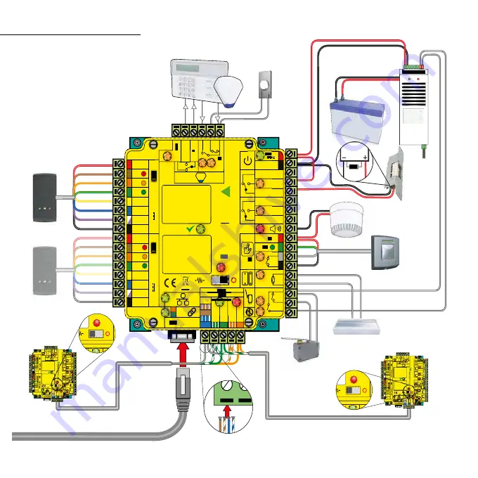
Page 5: ...Two typical site layouts are 1 The Net2 plus ACU s can be individually connected to the Net2 PC via the site LAN network 2 Using a RS485 daisy chain dataline a Net2 plus ACU can be used as a TCP IP converter for a line of Net2 plus ACU s When used with an RS485 data line on board termination resistors can be put in circuit with a simple slide switch Ensure that units installed in the middle of the...

Page 6: ...he door is shut When connected Net2 will check the door position during access activity and will raise an Alarm in the event of a Door Forced or Door left open condition Tamper switch The ACU supplied in a plastic housing has a NO tamper switch fitted and pre wired into the circuit board The Tamper LED will be ON when the switch is closed Net2 will monitor the switch position and will raise an Ala...

Page 7: ...n a plastic housing has a NO tamper switch fitted and pre wired into the circuit board The Tamper LED will be ON when the switch is closed Net2 will monitor the switch position and will raise an Alarm in the event of a Tamper condition Connect to a UL listed burglar alarm unit for supervision A fire alarm system must be used to release all fire doors External relay contacts are held closed by the ...

Page 8: ...play a single flashing red or green LED The reader or keypads default indication has all the LED s on Access granted is denoted with a single flashing Green LED Access Denied is a single flashing Red LED The minimum conductor gauge permitted to connect between the PSE or power injector and the powered device shall be 26 AWG This product is for indoor use only and is not intended for outside wiring...

Page 9: ...ort circuiting mutilation or incineration of the cells must be avoided to prevent one or more of the following occurrences Release of toxic materials release of hydrogen and or oxygen gas rise in surface temperature 2 If a cell has leaked or vented the control unit must be replaced The battery is not to be replaced End of line termination 120 ohm resistors must be linked across each data pair at t...

Page 10: ...C Paxton Net2 plus Net2 plus N C 12V DC PoE power supply in cabinet with Net2 plus 12V DC Outputs Combined data and power from a PSE Power source equipment This LED is on when the input supply is healthy This LED is on when the unit is operating in high power mode Ethernet data ...

Page 11: ... from Phihong injector models PoE31U 1At and PSA16U 480 Overview Input Voltage 36 57V DC Input Current 0 83 A 12V Output voltage 12 12 2V DC Load output current PoE 802 3at type 2 1 5 A Load output power PoE 802 3at type 2 20 4 W Load output current 802 3af 802 3at type 1 0 8 A Load output power 802 3af 802 3at type 1 10 36 W The PoE power supply can be used in the high power mode see specificatio...

Page 12: ...d This product is not suitable for retail sale All warranties are invalid if this product is not installed by a trained technician Maintenance 1 Mount the cabinet as instructed on the first page 2 Connect the network cable to PoE In 3 The Power LED will illuminate if power is available on this data line 4 The PoE LED will illuminate if the high power rating is available 5 12V DC power is available...

Page 13: ...D LED LED LED 12V DC 12V DC I Paxton Net2 plus Net2 plus 24V AC DC power supply with Net2 plus Note Must be powered by a UL 294 Listed Power supply or UL 603 Listed power limited power supply capable of supplying 24VDC 2 3 A 13 8V DC Outputs 24V DC Outputs Note ACinputhasbeenevaluatedbyULwhenused with CODEX model SEP 245OU OE6 transformer ...

Page 14: ... LED will illuminate when the input supply is healthy 4 12V DC power is available at the two output connectors 5 24V DC power is available at the two output connectors Input Connection Installation Following the completed installation of this equipment no further maintenance or testing is required It is advisable to ensure that any third party backup power supplies or recovery procedures are check...

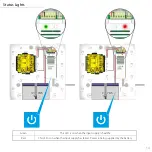
Page 15: ... 2 V 0 U S P V 0 12V 7Ah V 2 1 V 0 V 2 1 V 0 V 4 2 V 0 U S P V 0 12V 7Ah Status Lights Green This LED is on when the input supply is healthy Red This LED is on when the input supply has failed Power is being supplied by the battery ...

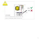
Page 16: ...15 12V 24V V 2 1 V 0 V 2 1 V 0 V 4 2 V 0 U S P V 0 12V 7Ah SAFETY WARNING RISK OF EXPLOSION IF BATTERY IS REPLACED BY AN INCORRECT TYPE DISPOSE OF USED BATTERIES ACCORDING TO THE INSTRUCTIONS ...

Page 17: ...V 12V 1 2 12V LED LED LED 12V LED LED LED LED 12V DC 12V DC 1 Paxton 12V 24V 12V LED V 0 12V 7Ah or 24 V DC 24V AC 12V DC 24V DC 12V DC or ON ON 24 V OFF 12 V SW 1 AUX AUX BAT BAT AC AC Note Must be powered by a UL 294 Listed Power limited Power supply or UL 603 Listed Power limited Power supply capable of supplying 24V AC 40 VA ...

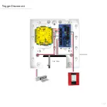
Page 18: ...UX AUX BAT BAT AC AC TRG1 TRG2 0V 0V 0V N C N O 2 COM N C N O COM Data D0 Clock D1 0V 10 100 Data D0 Clock D1 N O 12V 24V 12V 1 2 12V LED LED LED 12V LED LED LED LED 12V DC 12V DC 1 Paxton 12V 24V 12V LED Trigger Disconnect ...

Page 19: ...ovides DC output voltage when TRG1 and TRG2 are shorted together and are typically used to power Mag Locks STRIKE This terminal provides DC output voltage when TRG1 and TRG2 are unshorted and are typically used to power Electric Strikes N C N O C Isolated dry Form C contacts Shorting TRG1 and TRG2 together causes these contacts to switch They are typically used for controlling multiple AL177ULBs w...

Page 20: ...for power limited circuits trigger inputs dry outputs Keep power limited wiring separate from non power limited wiring AC input Battery Wires Minimum 0 25 spacing must be provided 4 Set the AL177ULB to the desired DC output voltage by setting switch SW1 1 2 to the appropriate position 5 Measure output voltage before connecting devices This helps avoiding potential damage 6 Connect battery to the t...

Page 21: ... 682 493 US 682 528 US 682 610 US 682 620 US 682 630 US 12 24V DC N A 12 24V DC N A N A 0 C 55 C 32 F 131 F 0 C 55 C 32 F 131 F N A N A N A N A N A N A 50 60Hz 24V AC DC 0 C 49 C 32 F 120 F 0 C 49 C 32 F 120 F 1 5 A 20 4 W 0 8 A 10 36 W N A N A N A N A 32 F 120 F N A N A N A 50 60Hz 24V AC DC 0 C 49 C 32 F 120 F N A N A 50 60Hz 24V AC 0 C 49 C 32 F 120 F 0 C 49 C 32 F 120 F 1 5 A 20 4 W 0 8 A 10 3...

Page 22: ...t2 Proximity Mullion Reader with Genuine HID Technology 400 175 US Proximity P75 Reader with Genuine HID Technology 400 275 US Proximity Keypad KP75 Reader with Genuine HID Technology Model Number Description Compatible UL listed Readers 857 600 US 1 N A N A N A 857 610 US 682 610 US 682 620 US 1 1 N A 4 4 3 857 630 US 682 493 US 682 528 US 682 630 US 1 1 N A 4 4 4 1 Destructive attack Model numbe...

Page 23: ...er and go into the Doors screen Click on the Detect button This should look for the ACU and then download its firmware This may take up to 5 minutes The OK LED should now be flashing with a steady heartbeat This procedure must only be done for one ACU at a time Please note If this unit is using the TCP IP interface any fixed IP settings will be retained If the unit is in DHCP mode it will need to ...

Page 24: ...gain and the OK LED will flash fast for a few seconds When the OK LED returns to a steady heartbeat the unit has completed the reset NOTE If this unit is using the TCP IP interface it will need to be detected again using the Server Config Utility as a new address may be issued by the DHCP server 5 Can we use a DHCP IP address The Ethernet interface does support DHCP but for more reliable communica...

Page 25: ...verkauf paxton gmbh de 44 0 1273 811011 paxton support support paxton co uk 8000 3570 3783 paxton support support paxtonaccess ae 33 0 1 57 32 93 56 support paxtonaccess fr paxton support 877 438 7298 usapaxton support supportUS paxton access com 52 55 5351 3667 paxton soporte soporte paxton access com 57 1508 8198 paxton soporte soporte paxton access com 32 0 78485147 paxton benelux support suppo...

Page 26: ...electrical installations The use of any add on expansion memory or other module manufactured or supplied by the manufacturer s representative will invalidate the CAN CSA certification This device complies with Industry Canada licence exempt RSS standard s Operation is subject to the following two conditions 1 this device may not cause interference and 2 this device must accept any interference inc...

Page 27: ...ns de sortie A UL pousser à faire bouton doit être utilisé Contact de porte A UL Normalement ouvert NO commutateur doit être utilisé Autoprotection Connectez vous à une unité d alarme antivol UL pour la supervision Alarme sonore Connexions à cette sortie d alarme n ont pas été évalués par l UL pour l utilisation de système d alarme Brise glace Un UL verre de rupture doit être utilisé Interface Por...

Page 28: ...26 03 2020 Paxton Ltd 1 0 7 Assembled in America Comprised of US and UK manufactured components ...

Reviews: