CAUTION:
This furnace is equipped with a manual
reset limit switch or fuse link in the gas control area. The
switch or fuse link opens and shuts off power to the gas
valve if a flame rollout or overheating condition occurs in
the gas control area. DO NOT bypass the switch. Correct
inadequate combustion air supply problem and reset the
switch or replace the fuse link.
Before operating the furnace, check each manual reset switch for
continuity. If necessary, press the button to reset the switch.
The blower compartment door must be in place to complete the
115-v circuit to the furnace.
B.
Sequence of Operation
CAUTION:
Furnace control must be grounded for
proper operation, or control will lockout. Control is
grounded through green wire routed to gas valve and
burner bracket screw.
Using the schematic diagram shown in Fig. 10, follow the
sequence of operation through the different modes. Read and
follow the wiring diagram very carefully.
NOTE:
If there is a power interruption and any thermostat call,
the control initiates a 90-sec blower only on period before starting
another cycle.
TABLE 5—ELECTRICAL DATA
UNIT SIZE
VOLTS—
HERTZ—
PHASE
OPERATING
VOLTAGE RANGE
MAXIMUM
UNIT AMPS
MINIMUM
WIRE GAGE
MAXIMUM
WIRE LENGTH (FT)‡
MAXIMUM
FUSE OR
HACR-TYPE CKT
BKR AMPS†
Maximum*
Minimum*
024045
115—60—1
127
104
6.0
14
47
15
036045
115—60—1
127
104
8.3
14
34
15
024065
115—60—1
127
104
5.9
14
47
15
036065
115—60—1
127
104
8.7
14
32
15
042091
115—60—1
127
104
9.0
14
31
15
048091
115—60—1
127
104
10.4
14
27
15
036111
115—60—1
127
104
8.0
14
35
15
048111
115—60—1
127
104
10.1
14
28
15
060111
115—60—1
127
104
14.4
12
31
20
048135
115—60—1
127
104
10.1
14
28
15
060135
115—60—1
127
104
13.3
12
33
20
060155
115—60—1
127
104
14.0
12
31
20
* Permissible limits of the voltage range at which the unit operates satisfactorily.
† Time-delay fuse is recommended.
‡ Length shown is as measured 1 way along wire path between unit and service panel for maximum 2 percent voltage drop.
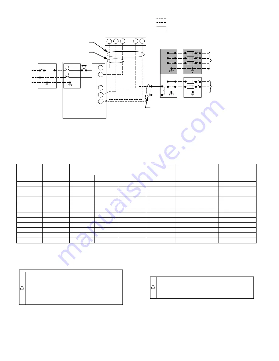
Fig. 8—Heating and Cooling Application Wiring Diagram
A95241
115-VOLT FIELD-
SUPPLIED
FUSED
DISCONNECT
AUXILIARY
J-BOX
CONTROL
BOX
24-VOLT
TERMINAL
BLOCK
THREE-WIRE
HEATING-
ONLY
FIVE
WIRE
NOTE 1
NOTE 2
FIELD-SUPPLIED
FUSED DISCONNECT
CONDENSING
UNIT
TWO
WIRE
FURNACE
R
G
C
W
C
R
G
Y
GND
GND
FIELD 24-VOLT WIRING
FIELD 115-, 208/230-, 460-VOLT WIRING
FACTORY 24-VOLT WIRING
FACTORY 115-VOLT WIRING
208/230- OR
460-VOLT
THREE
PHASE
208/230-
VOLT
SINGLE
PHASE
WHT
BLK
WHT
BLK
NOTES:
Connect Y-terminal as shown for proper operation.
Some thermostats require a "C" terminal connection as shown.
If any of the original wire, as supplied, must be replaced, use
same type or equivalent wire.
W
Y
GND
THERMOSTAT
TERMINALS
1.
2.
3.
—8—


