background image

10

MAXIMUM EQUIVALENT VENT LENGTH -- FT. (M) (CONTINUED)

NOTE: Maximum Equivalent Vent Length (MEVL) includes standard and concentric vent termination and does NOT include elbows.

Use Table 2 - Deductions from Maximum Equivalent Vent Length to determine allowable vent length for each application.

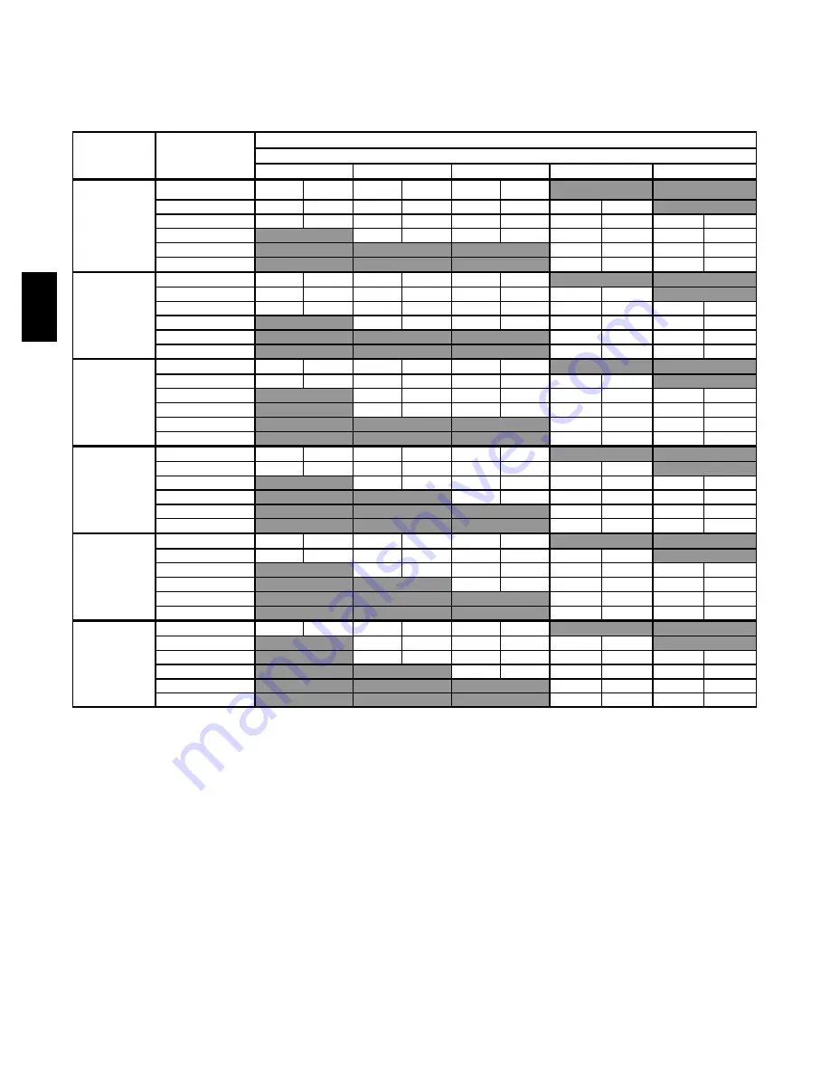
Table 3 – Maximum Equivalent Vent Length -- Ft. (M)

4501 to 10,000 Ft. (1371 to 3048 M) Altitude

Altitude

FT (M)

5

Unit Size

DIRECT VENT (2-PIPE) AND SINGLE-PIPE

Vent Pipe Diameter (in.)

1

1-1/2

2

2-1/2

3

4

4501 to 5000

(1370 to 1524)

40,000

33

(10.1)

171

(52.1)

196

(59.7)

NA

2

NA

60,000

20

(6.1)

111

(33.8)

198

(60.4)

221

(67.4)

NA

80,000

13

(4.0)

54

(16.5)

146

(44.5)

195

(59.4)

216

(65.8)

100,000

NA

16

(4.9)

91

(27.7)

200

(61.0)

222

(67.7)

120,000

NA

NA

NA

80

(24.4)

211

(64.3)

140,000

4

NA

NA

NA

60

(18.3)

134

(40.8)

5001 to 6000

(1524 to 1829)

40,000

27

(8.2)

158

(48.2)

179

(54.6)

NA

NA

60,000

16

(4.9)

103

(31.4)

186

(56.7)

207

(63.1)

NA

80,000

11

(3.4)

49

(14.9)

137

(41.8)

183

(55.8)

200

(61.0)

100,000

NA

12

(3.7)

85

(25.9)

188

(57.3)

208

(63.4)

120,000

NA

NA

NA

74

(22.6)

199

(60.7)

140,000

4

NA

NA

NA

50

(15.2)

109

(33.2)

6001 to 7000

(1829 to 2134)

40,000

21

(6.4)

145

(44.2)

162

(49.4)

NA

NA

60,000

13

(4.0)

96

(29.3)

174

(53.0)

194

(59.1)

NA

80,000

NA

44

(13.4)

120

(36.6)

171

(52.1)

185

(56.4)

100,000

NA

10

(3.0)

79

(24.1)

178

(54.3)

195

(59.4)

120,000

NA

NA

NA

68

(20.7)

187

(57.0)

140,000

4

NA

NA

NA

41

(12.5)

87

(26.5)

7001 to 8000

(2134 to 2438)

40,000

15

(4.6)

133

(40.5)

146

(44.5)

NA

NA

60,000

10

(3.0)

89

(27.1)

163

(49.7)

181

(55.2)

NA

80,000

NA

40

(12.2)

120

(36.6)

159

(48.5)

170

(51.8)

100,000

NA

NA

73

(22.3)

167

(50.9)

182

(55.5)

120,000

NA

NA

NA

62

(18.9)

175

(53.3)

140,000

4

NA

NA

NA

32

(9.8)

63

(19.2)

8001 to 9000

(2438 to 2743)

40,000

10

(3.0)

121

(36.9)

130

(39.6)

NA

NA

60,000

7

(2.1)

82

(25.0)

152

(46.3)

168

(51.2)

NA

80,000

NA

35

(10.7)

111

(33.8)

148

(45.1)

156

(47.5)

100,000

NA

NA

67

(20.4)

157

(47.9)

170

(51.8)

120,000

NA

NA

NA

56

(17.1)

164

(50.0)

140,000

4

NA

NA

NA

23

(7.0)

42

(12.8)

9001 to 10,000

(2743 to 3048)

40,000

5

(1.5)

110

(33.5)

115

(35.1)

NA

NA

60,000

NA

76

(23.2)

142

(43.3)

156

(47.5)

NA

80,000

NA

31

(9.4)

103

(31.4)

137

(41.8)

142

(43.3)

100,000

NA

NA

62

(18.9)

147

(44.8)

157

(47.9)

120,000

NA

NA

NA

51

(15.5)

153

(46.6)

140,000

4

NA

NA

NA

16

(4.9)

20

(6.1)

NOTES

:

1. Use only the vent pipe sizes shown for each furnace. It is NOT necessary to choose the smallest diameter pipe possible for venting.
2. NA --- Not allowed. Pressure switch will not close, or flame disturbance may result.
3. Total equivalent vent lengths under 10’ for 40,000 BTUH furnaces from 0 to 2000 ft. (0 to 610 M) above sea level require use of an outlet choke plate .

Failure to use an outlet choke when required may result in flame disturbance or flame sense lockout.

4. Not all furnace families include 140,000 BTUH input models.
5. Vent sizing for Canadian installations over 4500 ft (1370 M) above sea level are subject to acceptance by local authorities having jurisdiction.
6. Size both the combustion air and vent pipe independently, then use the larger size for both pipes.
7. Assume the two 45

_

elbows equal one 90

_

elbow. Wide radius elbows are desirable and may be required in some cases.

8. Elbow and pipe sections within the furnace casing and at the vent termination should not be included in vent length or elbow count.
9. The minimum pipe length is 5 ft. (1.5 M) linear feet (meters) for all applications.

10. Use 3---in. (76 mm) diameter vent termination kit for installations requiring 4---in. (102 mm) diameter pipe.

PG96V

A

T

Summary of Contents for PG96VAT

Page 1: ...ice S Silicon Nitride Hot Surface Igniter S 4 way multipoise design for upflow downflow or horizontal installations with unique vent elbow and optional through the cabinet downflow venting capability S Full featured variable speed blower motor two speed inducer motor and two stage gas valve S Self diagnostics S Adjustable blower speed for cooling continuous fan and dehumidification S Aluminized st...

Page 2: ...ormance and success These innovations paired with the continuation of a crimped no weld seam create an efficient robust design for this essential component The condensing heat exchanger a stainless steel fin and tube design is positioned in the furnace to extract additional heat Stainless steel coupling box componentry between heat exchangers has exceptional corrosion resistance in both natural ga...

Page 3: ...x 10 11 x 10 11 x 11 Air Filtration System Field Supplied Filter Used for Certified Watt Data KGAWF 06UFR Electrical Data 30040 42060 48080 60080 60100 66120 Input Voltage Volts Hertz Phase 115 60 1 Operating Voltage Range Min Max 104 127 Maximum Input Amps Amps 7 5 9 2 9 2 11 7 11 8 11 8 Unit Ampacity Amps 10 3 12 4 12 4 15 5 15 6 15 6 Minimum Wire Size AWG 14 14 14 12 12 12 Maximum Wire Length M...

Page 4: ... 5 95 AFUE 6 96 AFUE 7 97 AFUE 24 800 CFM 30 1000 CFM 36 1200 CFM 42 1400 CFM 48 1600 CFM 54 1800 CFM 60 2000 CFM 66 2200 CFM 0 5 ESP Example of a Model Number A12375 FURNACE COMPONENTS RATING PLATE NOT SHOWN LOCATED ON BLOWER DOOR GAS VALVE MAIN LIMIT SWITCH BEHIND GAS VALVE REPRESENTATIVE DRAWING ONLY SOME MODELS MAY VARY IN APPEARANCE ELECTRICAL JUNCTION BOX IF REQUIRED LOCATION MAY VARY OPERAT...

Page 5: ... Kit LP to Nat KGAPN42011SP D D D D D D Gas Orifice Kit 42 Nat Gas LH32DB207 D D D D D D Gas Orifice Kit 43 Nat Gas LH32DB202 D D D D D D Gas Orifice Kit 44 Nat Gas LH32DB200 D D D D D D Gas Orifice Kit 45 Nat Gas LH32DB205 D D D D D D Gas Orifice Kit 46 Nat Gas LH32DB208 D D D D D D Gas Orifice Kit 47 Nat Gas LH32DB078 D D D D D D Gas Orifice Kit 48 Nat Gas LH32DB076 D D D D D D Gas Orifice Kit 5...

Page 6: ...20 435 See note 4 OFF ON OFF 780 725 660 615 540 See note 4 OFF ON ON 975 925 875 835 785 750 690 655 610 570 ON OFF OFF 1160 1120 1090 1045 1010 970 920 885 840 800 ON OFF ON 1330 1295 1260 1220 1190 1150 1110 1075 1045 1005 ON ON OFF 1705 1650 1595 1545 1475 1415 1340 1275 1200 1105 ON ON ON 1705 1650 1595 1545 1475 1415 1340 1275 1200 1105 Clg SW2 Maximum Clg Airflow 2 1705 1650 1595 1545 1475 ...

Page 7: ...ch Settings External Static Pressure ESP SW2 3 SW2 2 SW2 1 0 1 0 2 0 3 0 4 0 5 0 6 0 7 0 8 0 9 1 0 66120 6 Clg Default OFF OFF OFF 2010 1960 1910 1850 1800 1750 1690 1645 1565 1480 Cooling SW2 OFF OFF ON 1015 805 645 550 480 See note 4 OFF ON OFF 1075 975 915 835 765 See note 4 OFF ON ON 1205 1135 1055 1000 935 See note 4 ON OFF OFF 1400 1330 1260 1190 1145 1080 1035 970 905 845 ON OFF ON 1615 155...

Page 8: ...A NA 60 000 23 7 0 119 36 3 210 64 0 235 71 6 NA 80 000 15 4 6 59 18 0 155 47 2 210 64 0 232 70 7 100 000 NA 19 5 8 98 29 9 211 64 3 236 71 9 120 000 NA NA 8 2 4 86 26 2 224 68 3 140 000 4 NA NA NA 79 24 1 158 48 2 4001 to 4500 1219 to 1370 40 000 36 11 0 177 53 9 205 62 5 NA NA 60 000 21 6 4 115 35 1 204 62 2 228 69 5 NA 80 000 14 4 3 56 17 1 150 45 7 202 61 6 224 68 3 100 000 NA 17 5 2 94 28 7 2...

Page 9: ...ent Vent Length TEVL 112 ft Add all of the above lines Maximum Equivalent Vent Length MEVL 127 ft For 2 pipe from Table 1 Is TEVL less than MEVL YES Therefore 2 pipe may be used Example 2 A direct vent 60 000 Btuh furnace installed at 2100 ft 640 M Venting system includes FOR EACH PIPE 100 feet 30 M of vent pipe 95 feet 28 M of combustion air inlet pipe 3 90_ long radius elbows and a polypropylene...

Page 10: ... 8 63 19 2 8001 to 9000 2438 to 2743 40 000 10 3 0 121 36 9 130 39 6 NA NA 60 000 7 2 1 82 25 0 152 46 3 168 51 2 NA 80 000 NA 35 10 7 111 33 8 148 45 1 156 47 5 100 000 NA NA 67 20 4 157 47 9 170 51 8 120 000 NA NA NA 56 17 1 164 50 0 140 000 4 NA NA NA 23 7 0 42 12 8 9001 to 10 000 2743 to 3048 40 000 5 1 5 110 33 5 115 35 1 NA NA 60 000 NA 76 23 2 142 43 3 156 47 5 NA 80 000 NA 31 9 4 103 31 4 ...

Page 11: ... 44 8 0 20 Ft 20 0 32 0 30 0 22 0 11 0 20 0 70 0 104 0 87 0 67 0 20 0 70 0 124 0 104 0 82 0 M 6 1 9 8 9 1 6 7 3 4 6 1 21 3 31 7 26 5 20 4 6 1 21 3 37 8 31 7 25 0 20 30 Ft 20 0 17 0 14 0 6 0 0 0 20 0 70 0 71 0 57 0 40 0 20 0 70 0 86 0 71 0 52 0 M 6 1 5 2 4 3 1 8 0 0 6 1 21 3 21 6 17 4 12 2 6 1 21 3 26 2 21 6 15 8 40 40 Ft 15 0 7 0 5 0 0 0 0 0 20 0 61 0 52 0 40 0 24 0 20 0 70 0 64 0 50 0 33 0 M 4 6 ...

Page 12: ...PLY AIR A10490 MINIMUM CLEARANCES TO COMBUSTIBLE MATERIALS POSITION CLEARANCE Rear 0 0 mm Front Combustion air openings in furnace and in structure 1 in 25 mm Required for service 24 in 610 mm All Sides of Supply Plenum 1 in 25 mm Sides 0 0 mm Vent 0 0 mm Top of Furnace 1 in 25 mm Recommended Consult your local building codes COMBUSTION AIR PIPE FOR NON DIRECT 1 PIPE VENT APPLICATION FIELD SUPPLIE...

Page 13: ...5 8 600 2 24 1 2 622 Furnace with or without Cased Coil Assembly or Coil Box 22 1 8 562 19 483 23 3 4 603 20 5 8 600 1 The plenum should be constructed 1 4 in 6 mm smaller in width and depth than the plenum dimensions shown above Concentric Vent Kit A93086 A concentric vent kit allows vent and combustion air pipes to terminate through a single exit in a roof or side wall One pipe runs inside the o...

Page 14: ...IELD 24 V WIRING FIELD 115 208 230 460 V WIRING FACTORY 24 V WIRING FACTORY 115 V WIRING 208 230 OR 460 V THREE PHASE 208 230 V SINGLE PHASE BLOWER DOOR SWITCH WHT BLK WHT BLK NOTES Connect Y terminal in furnace as shown for proper blower operation Some thermostats require a C terminal connection as shown If any of the original wire as supplied must be replaced use same type or equivalent wire W Y...

Page 15: ...ATION NOTE ALL DIMENSIONS IN INCH MM 22 2 7 8 7 8 22 2 POWER CONN AIR FLOW SEE NOTE 3 NOTES 1 Doors may vary by model 2 Minimum return air openings at furnace based on metal duct If flex duct is used see flex duct manufacturer s recommendations for equivalent diameters a For 800 CFM 16 in 406 mm round or 14 1 2 x 12 in 368 x 305 mm rectangle b For 1200 CFM 20 in 508 mm round or 14 1 2 x 19 1 2 in ...

Page 16: ...at exchangers shall be 3 Pass corrosion resistant aluminized steel of fold and crimp sectional design and applied operating under negative pressure Secondary Heat Exchangers Secondary heat exchangers shall be of a stainless steel flow through of fin and tube design and applied operating under negative pressure Controls Controls shall include a micro processor based integrated electronic control bo...

Reviews: