These furnaces are shipped with the following materials to assist in proper furnace installation. These materials are shipped in the main blower
compartment.
Installer Packet includes:
Installation Manual
Service Guide
User’s Information Manual
Warranty Certificate
Loose Parts Bag includes:
Quantity
Pressure tube extension
1
Collector box or condensate trap extension tube
1
Inducer housing drain tube
1
1/2-in. CPVC street elbow
2
Drain tube coupling
1
Drain tube coupling grommet
1
Vent and combustion-air pipe support
2
Condensate trap hole filler plug
3
Vent and combustion-air intake hole filler plug
2
Combustion-air pipe perforated disk assembly
1
Vent Pipe Extension (ONLY supplied with some furnaces)
1
For accessory installation details, refer to accessory installation instructions.
CODES AND STANDARDS
Follow all national and local codes and standards in addition to these instructions. The installation must comply with regulations of the
serving gas supplier, local building, heating, plumbing, and other codes. In absence of local codes, the installation must comply with the national
codes listed below and all authorities having jurisdiction.
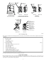
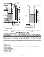
Fig. 5—Condensate Trap
A93026
1
⁄
2
OD
INDUCER HOUSING
DRAIN CONNECTION
1
⁄
4
OD
COLLECTOR BOX TO
TRAP RELIEF PORT
5
⁄
8
OD
COLLECTOR BOX
DRAIN CONNECTION
1
⁄
2
-IN. PVC OR CPVC
SCREW HOLE FOR
UPFLOW OR DOWN-
FLOW APPLICATIONS
(OPTIONAL)
1 4
2
7 8
1 8
7
SLOT FOR SCREW
HORIZONTAL
APPLICATION
(OPTIONAL)
WIRE TIE
GUIDES
(WHEN USED)
1 2
1
3 4
1
3 4
FRONT VIEW
SIDE VIEW
FURNACE
DOOR
FURNACE
DOOR
CONDENSATE
TRAP
78
1 4
26
4
FURNACE
SIDE
FURNACE
SIDE
1 2
1
1 4
26
4
3 4
5
3 4
5
4
SIDE VIEW
FRONT VIEW
END VIEW
FRONT VIEW
3 4
DOWNFLOW AND ALTERNATE
EXTERNAL UPFLOW APPLICATIONS
HORIZONTAL
APPLICATIONS
FIELD
DRAIN
CONN
FIELD
DRAIN
CONN
CONDENSATE
TRAP (INSIDE)
BLOWER SHELF
ALTERNATE DRAIN
TUBE LOCATION
UPFLOW APPLICATIONS
CONDENSATE TRAP
DRAIN TUBE LOCATION
—6—
Summary of Contents for PG9MAA
Page 70: ... 70 ...
Page 71: ... 71 ...


