background image

DCH-4000P-xx series Receivers


- 16 - 

W W W . P B I - C H I N A . C O M   


Summary of Contents for DCH-4000P

Page 1: ...DCH 4000P Series Professional Digital Decoder User Manual ...

Page 2: ... REAR PANEL 6 5 1 Power Supply 6 5 2 Output Connectors 6 5 3 ASI Input Connector 7 5 4 RS 232 Interface 7 5 5 Ethernet Interface 7 5 6 TS IP Interface Factory Optional 7 6 INSTALLATION 7 6 1 Main Menu 7 6 2 System Menu 8 6 2 1 Local Setup 8 6 2 2 Setting up the Trap IP Address 8 6 2 3 Editing the Unit Name 9 6 2 4 Checking the Properties 9 6 2 5 Recover Factory Default Settings 9 6 2 6 Setting Mac...

Page 3: ...41C 41S2 18 8 2 1 Checking Status of Inputs 18 8 2 2 Setting the Tuner Parameters 18 8 2 3 Setting the Ethernet Connector 18 8 3 Setting Outputs for DCH 4000P 41S 41T 41C 41S2 19 9 Manual for DCH 4000P 42S 42T 42C 42S2 19 9 1 Menu Structure for DCH 4000P 42S 42T 42C 42S2 19 9 2 Setting Inputs for DCH 4000P 42S 42T 42C 42S2 21 9 3 Setting Outputs for DCH 4000P 42S 42T 42C 42S2 22 9 3 1 Setting the ...

Page 4: ... remove covers For the correct and safe use of the device it is essential that both operating and servicing personnel follow generally accepted safety procedures in addition to the safety precautions specified in this manual Whenever it is likely that safety protection is impaired the device must be made in operative and secured against unintended operation The appropriate servicing authority must...

Page 5: ...ices Management System a remote management software 2 1 Features z Fully complies with MPEG 2 MP ML and DVB S T C standards z IP input or output with UDP RTP optional z Multicast and Unicast on IP z Supports PAL NTSC or SECAM z Supports various Conditional Access systems z SDI video output with digital audio embedded z Two sets of independent ASI outputs z Automatic PMT update z Compatible with Mu...

Page 6: ...to select Frequency 47 to 63 Hz Power 50 VA max 30 VA typical Current 110 V 0 27A or 240 V 0 125A typical Caution Be sure the supply voltage is within the specified range Checking the fuses The recognized recommended fuses are size 5 by 20 mm rate T 2 0A 250 V UL and IEC approved The line fuse is housed in a small container besides the power connector on the rear panel To check the fuse insert the...

Page 7: ... of the device and the fans inside The air flow should not be obstructed Therefore the device has to be placed on a flat surface leaving some space at the sides of the device When in operation the internal temperature should not exceed the limit of 70 4 FRONT PANEL 4 1 Front Panel List Figure 4 1 Front Panel of DCH 4000P xx Series Receiver 4 2 Indicator LEDs There are 3 LED indicators POWER the st...

Page 8: ...f DCH 4000P xx series The 6 keys on the front panel allow you to navigate in the information given on the LCD and to change parameters when the device operates under local control The ENTER key is used to enter the main menu or a sub menu When you stand on the preferred menu ENTER is used to active the parameter on the bottom line and allows you to change the value It also finishes the input of ne...

Page 9: ...15 B16 L Audio R interface B20 Ethernet interface for remote management system B21 Grounding 5 1 Power Supply The power cord is inserted to an IEC main socket at the side of the device Check that the power cord is suitable for the country where the device will be used A standard power cord with a European DIN 49441 two pin main plug is delivered together with the device The line fuses are housed i...

Page 10: ... connector B20 provides a remote control interface 5 6 TS IP Interface Factory Optional An RJ 45 connector B1 provides a streaming stream over IP input or output 6 INSTALLATION The device allows you to configure control and monitor through the Keypad and front panel display when a remote control system is not used 6 1 Main Menu Turn on the device and wait for 8 to 10 seconds while the device will ...

Page 11: ...rol system such as the HDMS IP Address The IP address for the unit Network Mask The network mask for the subnet to which the unit is connected Gateway The gateway for the network to which this unit is connected 6 2 2 Setting up the Trap IP Address The DCH 4000P xx provides a Monitor Center IP address You can set this to be the same IP address of the Monitor Center which is typically a PC in order ...

Page 12: ...ress FW Version the version of the FPGA software SW Version the version of the main software 6 2 5 Recover Factory Default Settings All the user configurable parameters will be set to the factory default settings including IP address and the unit name Note that the unit will not be connected with the HDMS remote management system until the IP is properly configured 6 2 6 Setting Machine Type This ...

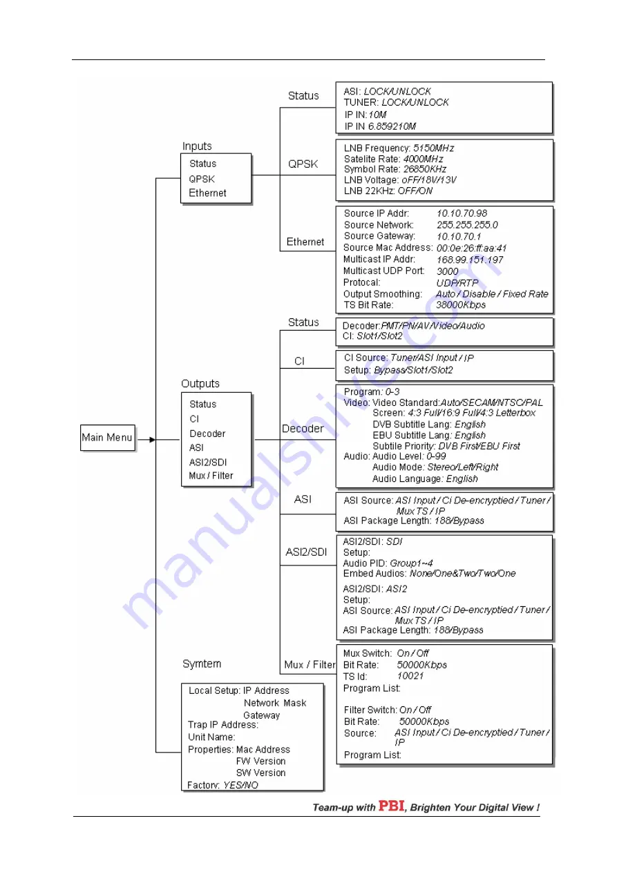
Page 13: ...DCH 4000P xx series Receivers 10 W W W P B I C H I N A C O M Figure 7 1 Full Menu Structure for DCH 4000P 30S ...

Page 14: ...t Menu you can monitor and configure the parameters of the Tuner 7 2 1 Checking Status of Inputs ASI Input locked or unlock indicate the status of the ASI input Tuner Input when the QPSK QAM COFDM signal is locked by the tuner the bit rate is displayed on the bottom row of LCD 7 2 2 Setting the Tuner Parameters To receive the QPSK QAM COFDM signal these parameters below must be set to appropriate ...

Page 15: ... proper value in KBaud For COFDM Tuner Frequency enter the proper frequency of the COFDM signal in MHz For DVB S2 Tuner LNB Local Oscillator L O Freq enter the frequency of LNB in MHz Satellite Freq edit the satellite down link frequency in MHz The IF frequency will be calculated automatically Symbol Rate enter the QPSK 8PSK symbol rate LNB Voltage select the correct LNB voltage output of the F co...

Page 16: ...30S 30T 30C 30S2 7 3 1 Checking Status of Outputs There are 2 displays on the LCD for monitoring the status of the decoder and the common interface Decoder OK or Alarms indicates the status of the decoder You can use the ENTER key to check detailed information in the submenu of the Decoder CI You can check the information of the CAM Modules in Slot1 and Slot2 ...

Page 17: ...ress the or key to select the program which is expected to be decoded Press the and key to choose channel from 0 to 3 then press the ENTER key to confirm 0 xxxxx displays the program name which comes from ASI input 1 xxxxx displays the program name which comes from TUNER input 2 xxxxx displays the program name which comes from TS IP input this is invalid for 30 10S 11T 12C 13S2 series 3 xxxxx disp...

Page 18: ... there are 4 options none one two two and one 7 3 6 Setting the Mux Filter Note the Mux Filter are alternative For Mux Mux Switch the internal multiplexer could be switched On Off Bit Rate set the output bit rate of the multiplexed TS in Kbps TS ID you can configure the TS ID to mark the multiplexed TS Program List the list of programs multiplexed Press the ENTER key to select the program which is...

Page 19: ...DCH 4000P xx series Receivers 16 W W W P B I C H I N A C O M ...

Page 20: ...000P xx series Receivers 17 W W W P B I C H I N A C O M Figure 8 1 Full Menu Structure for DCH 4000P 41S Figure 8 2 Inputs Menu Structure for DCH 4000P 41T Figure 8 3 Inputs Menu Structure for DCH 4000P 41C ...

Page 21: ...ort stream over IP input The bitrate is displayed on the bottom row of the LCD if IP input is valid 8 2 2 Setting the Tuner Parameters Please refer to paragraph 7 2 2 8 2 3 Setting the Ethernet Connector There is an Ethernet connector for receiving transport stream over IP The Ethernet connector has user configurable IP address network mask and default gateway These must be set to appropriate valu...

Page 22: ... TS IP input Auto the bit rate is variable Disable the unit let the TS pass by Fixed Rate the bitrate is fixed TS Bit Rate set the bit rate of the TS comes from the TS IP input The setting is only valid when the output smoothing is configured as Fixed Rate 8 3 Setting Outputs for DCH 4000P 41S 41T 41C 41S2 Please refer to paragraph 7 3 for the setting method Note that the TS over IP input also cou...

Page 23: ...DCH 4000P xx series Receivers 20 W W W P B I C H I N A C O M ...

Page 24: ...Structure for DCH 4000P 42S Figure 9 2 Inputs Menu Structure for DCH 4000P 42T Figure 9 3 Inputs Menu Structure for DCH 4000P 42C Figure 9 4 Inputs Menu Structure for DCH 4000P 42S2 9 2 Setting Inputs for DCH 4000P 42S 42T 42C 42S2 Please refer to paragraph 7 2 for the setting method ...

Page 25: ...DCH 4000P xx series Receivers 22 W W W P B I C H I N A C O M 9 3 Setting Outputs for DCH 4000P 42S 42T 42C 42S2 Figure 9 5 Outputs Menu Structure for DCH 4000P 42S 42T 42C 42S2 ...

Page 26: ...er of the TS packages encapsulated in one UDP package The valid range goes from 1 to 7 Time To Live set the number of the routers over which the TS over IP can be transmitted The valid range goes from 1 to 5 Type of Service select the type of service There are Normal Min Monetary Cost Max Reliability Max Throughput or Min Delay optional Source select the source of the TS over IP streaming output T...

Page 27: ...for adding one or a group of DCH 4000P xx please refer to the HDMS Reference Guide 10 5 DCH 4000P xx in HDMS Double click on the device in the Devices Management window to open the console of the DCH 4000P xx The HDMS provides full operation to the DCH 4000P xx Parameters are grouped in three panels The Input Setting which gives the full operation on inputs parameters The Output Setting allows the...

Page 28: ... necessary parameters are set properly If not please set the parameters properly If the signal still cannot be locked please check whether the quality of the signal is out of the threshold of the Tuner If not then the device might be damaged please contact the agent for support 3 Why can the ASI not be locked Answer Please make sure the BNC cable is connected well and there are programs transmitte...

Page 29: ...32 off FEC Code Rate 1 2 2 3 3 4 5 6 and 7 8 DS3 Input Input Impedance 75 Ω Connector BNC Maximum Input Code Rate 44 736 Mbit s Format Unframed Framing according to G 804 G 752 DS3 DS3 Loop Through Output Impedance 75 Ω Maximum Output Code Rate 44 736 Mbit s Connector BNC Format Unframed Framing according to G 804 G 752 DS3 TS over IP Output Connector 100 base T RJ45 Output Bit Rate 70 Mbits s Max...

Page 30: ...rs 27 W W W P B I C H I N A C O M Audio XRL Balance Output 1 General Operating Temperature 0 45 Storage Temperature 20 70 Humidity 85 Power Supply AC 90V 260V 50Hz 60Hz Dimensions 483 mm 255 mm 44 mm Approximately Net Weight 5 kg ...

Page 31: ...it is the property of Pro Broadband Inc and may be the subject of patents pending and granted It must not be used for commercial purposes nor copied disclosed reproduced stored in a retrieval system or transmitted in any form or by any means electronic mechanical photocopying recording or otherwise whether in whole or in part without Pro Broadband Inc s prior written agreement 2007 Pro Broadband I...

Reviews: