background image

5

Assembly Instructions

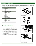
The model ATV-MX160 boom requires some assembly.  Follow the step-by-step instructions to ensure proper assembly.  Before 

assembling, ensure that you have all of the necessary components and parts.

160” Boom Kit Box

Ref.

Qty. Description

1

Center boom section

1

Right boom wing section

1

Left boom wing section

1

Boom hardware kit (Figure 1)

a

2

Boom mounting clip

b

2

1” x 8” extension spring

c

3

Stainless steel hose clamp

d

8

3/8” flange nut

e

4

3/8” flat washer

f

4

3/8” acorn nut

g

2

3/8” x 1” carriage bolt

h

6

3/8” x 2” carriage bolt

1

Nozzle kit (Figure 2)

a

8

Purple polymer spray tip

b

8

Red mesh tip strainer

c

8

Rubber Washer

d

8

Black nozzle cap

d

Figure 1: Boom hardware kit

a

c

b

Figure 2: Nozzle kit

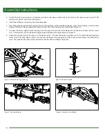
Figure 4: Boom wing mounting

Figure 3: Center frame mounting

a

b

Assembly Instructions

1.  Bolt the boom mounting clips (c) to the center section 

(a), using  3/8” x 2” bolts (d) and 3/8” flange nuts (e).  Bolt 

the boom mounting clips to the sprayer frame using 3/8” 

x 1” bolts (b) and 3/8” flange nuts (e) (Figure 3).

2.  Position the right boom wing (a) as shown and insert the 

3/8” x 2” bolts (b) through the holes in the boom wing 

hinge and the center frame.  Fasten the bolts with 3/8” 

flange nuts (c) (Figure 4). 

3.  Rotate the boom wing towards the center frame to the 

closed position.

c

d

e

a

c

b

e

d

f

g

h

a

c

b

Summary of Contents for CropCare ATV-MX160

Page 1: ...13 Manual Fold Boom Model ATV MX160 Form ATV MX160OM Revision A Rev Date 01 17 Manufactured PBZ LLC A Paul B Zimmerman Inc Company www CropCareEquipment com Owner s Manual...

Page 2: ...2 Notes...

Page 3: ...d understand this manual and its instructions and warnings completely before operating Before You Begin 3 Safety Precautions 4 Before Operation 4 During Operation 4 Following Operation 4 Towing the Sp...

Page 4: ...with chemical application guidelines Be aware of dangerous terrain such as holes slopes drop offs banks rocks and hidden hazards Operate the tractor and sprayer up and down slopes not across Allow fo...

Page 5: ...1 Nozzle kit Figure 2 a 8 Purple polymer spray tip b 8 Red mesh tip strainer c 8 Rubber Washer d 8 Black nozzle cap d Figure 1 Boom hardware kit a c b Figure 2 Nozzle kit Figure 4 Boom wing mounting...

Page 6: ...ly hose a coming from the sprayer tank to the white barbed tee on the center boom section Insert the 1 2 barbed tee b into the boom supply line and tighten with a hose clamp c Figure 7 8 Slide hose cl...

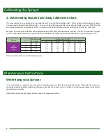
Page 7: ...the sprayer or equipment 2 Determine the nozzle size and consult the calibration chart for the desired or instructed Gallons per Acre GPA Calibrating the Sprayer 1 Calculating the Speed It is importan...

Page 8: ...chart you find that you should set the sprayer s pressure at about 29 psi in order to apply 13 GPA Tip Size PSI GPM of one nozzle Gallons Per Acre GPA 3 MPH 4 MPH 5 MPH 6 MPH AIXR Lavender 110025 15...

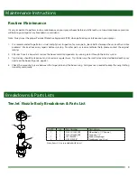
Page 9: ...nozzle on the boom Figure 6 page 6 4 Check the amount of grease between the hinge plate and the boom wing Add grease as needed to keep the wing folding smoothly and quietly It is very important to pe...

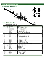
Page 10: ...Bolt Carriage 3 8 16 x 2 1 2 Gr 5 17 6 CB38 2G5 Bolt Carriage 3 8 16 x 2 Gr 5 18 2 CB38 312G5 Bolt Carriage 3 8 16 x 3 1 2 Gr 5 19 4 CC5520 Cap Poly Square 1 1 4 x 14 20 Ga Blk 20 2 CN38 118 Nut Coup...

Page 11: ...iginal retailer CropCare hereby provides a Limited One 1 Year Warranty on the Products manufactured by CropCare that such Products shall be free from manufacturer s defects in any of the Product s com...

Page 12: ...Manufactured by PBZ LLC A Paul B Zimmerman Inc Company www CropCareEquipment com...

Reviews: