background image

29

Chapter 4: Software & Applications

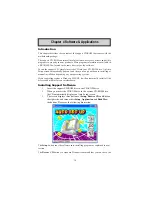
contents of the disc with the Windows file browsing interface.

The 

Exit

 button closes the Auto Setup window. To run the program again, reinsert

the CD-ROM disc in the drive; or click the CD-ROM driver from the Windows
Explorer, and click the Setup icon.

The 

Application

 button brings up a software menu. It shows the bundled software

that this mainboard supports.

The 

ReadMe

 brings you to the Install Path where you can find out path names of

software driver.

Auto-Installing under Windows 98/2000/XP

If you are under Windows 98/2000/XP, please click the 

Setup

 button to run the

software auto-installing program while the Auto Setup screen pops out after
inserting the support CD-ROM:

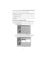
1

The installation program loads and displays the following screen.

Click the 

Next

 button.

2

Select the items that you want to setup by clicking on it (the default

options are recommended). Click the 

Next

 button to proceed.

Summary of Contents for A33G Series

Page 1: ...regis tered trademarks of Advanced Micro Devices Inc Microsoft MS DOS and Windows 2000 XP are registered trademarks of Microsoft Corporation AMI is a registered trademark of American Megatrends Inc Other names used in this publication may be trademarks and are acknowledged Static Electricity Precautions 1 Don t take this motherboard and components out of their original static proof package until y...

Page 2: ...14 Expansion Slots 16 Chapter 3 BIOS Setup Utility 18 Introduction 18 Running the Setup Utility 18 Standard CMOS Setup Page 19 Advanced Setup Page 20 Features Setup Page 21 Power Management Setup Page 23 PCI Plug and Play Setup Page 24 BIOS Security Features Setup Page 25 CPU PnP Setup Page 25 Hardware Monitor Page 26 Load Best Performance Settings 27 Load Optimal Defaults 27 Save Changes and Exit...

Page 3: ...partment has already tested and verified these drivers Just click the Continue Anyway button and go ahead the installation 2 USB 2 0 Driver Limitations 2 1 The USB 2 0 driver only supports Windows XP and Windows 2000 2 2 If you connect a USB 2 0 hub to the root hub plugging USB devices into this hub the system might not successfully execute certain USB devices connection because it could not recog...

Page 4: ...motherboard This motherboard is a Micro ATX size motherboard and has power connectors for an ATX power supply Key Features The key features of this motherboard include Socket AM2 Processor Support Supports AMD Sempron Athlon 64 Athlon 64 X2 Dual Core Athlon 64 FX processors Supports Front Side Bus 1000 MHz Note HyperTransport Technology is a point to point link between two devices it enables integ...

Page 5: ...rogrammable Input Output and DMA Direct Memory Access modes Supports IDE Ultra DMA bus mastering with transfer rates of 133 100 66 MB sec Serial ATA Two Serial ATA Connectors Transfer rate exceeding best ATA 1 5 Gb s with scalability to higher rates Low pin count for both host and devices AC 97 Codec Onboard I O Ports Two PS 2 ports for mouse and keyboard One serial port One parallel port One VGA ...

Page 6: ...low speed signaling and one EHCI Host Controller core for high speed signaling Root hub consists 4 downstream facing ports with integrated physical layer transceivers shared by UHCI and EHCI Host Controller up to eight functional ports Support PCI Bus Power Management Interface Specification release 1 1 Legacy support for all downstream facing ports BIOS Firmware This motherboard uses AMI BIOS tha...

Page 7: ...bon cable The Software support CD Optional Accessories You can purchase the following optional accessories for this motherboard The Extended USB module The CNR v 90 56K Fax Modem card The SerialATAcable The Serial ATA power cable Note You can purchase your own optional accessories from the third party but please contact your local vendor on any issues of the specification and compatibility ...

Page 8: ...Install this motherboard in a system chassis case Connect any extension brackets or cables to headers connectors on the motherboard Install peripheral devices and make the appropriate connections to headers connectors on the motherboard Note 1 Before installing this motherboard make sure jumper CLR_CMOS1 is under Normal setting See this chapter for information about locating CLR_CMOS1 and the sett...

Page 9: ...ive connector 7 IDE1 Primary IDEconnector 8 IDE2 Secondary IDEconnector 9 F_USB1 2 Front Panel USB headers 10 SATA1 2 Serial ATA connectors 11 PANEL1 Front Panel Sw itch LED header 12 SYS_FAN1 System Fan connector 13 SPK1 Speaker header 14 CLR_CMOS1 Clear CMOS jumper 15 PCI1 2 32 bit PCI slots 16 CNR1 CNR slot 17 SPDIFO1 SPDIF Out header 18 CD_IN1 Analog Audio Input header 19 PCI E2 PCI Express x1...

Page 10: ...onnect a PS 2 pointing device PS 2 Keyboard Use the lower PS 2 port to connect a PS 2 keyboard Parallel Port LPT1 Use the Parallel port to connect printers or other parallel communications devices Serial Port COM1 Use the COMport to connect serial devices such as mice or fax modems COM1 is identified by the systemas COM1 VGA Port Use the VGA port to connect VGA devices LANPort optional Connect an ...

Page 11: ...he top of the CPU 5 Install the cooling fan heatsink unit onto the CPU and secure them all onto the socket base 6 Plug the CPU fan power cable into the CPU fan connector CPU_FAN1 on the motherboard Installing Memory Modules This motherboard accommodates two 240 pin DIMM sockets Dual Inline Memory Module for unbuffered DDR2 800 667 533 400 memory modules Double Data Rate SDRAM and maximum 16 GB ins...

Page 12: ...ion Procedure These modules can be installed with up to 16 GB system memory Refer to the following to install the memory module 1 Push down the latches on both sides of the DIMM socket 2 Align the memory module with the socket There is a notch on the DIMM socket that you can install the DIMM module in the correct direction Match the cutout on the DIMM module with the notch on the DIMM socket 3 Ins...

Page 13: ...ap into the CLEAR setting for a few seconds Function Jumper Clear CMOS Short Pins 1 2 NORMAL Short Pins 2 3 Jumper Settings Connecting two pins with a jumper cap is SHORT removing a jumper cap from these pins OPEN Note for dual channel DDR2 1 You CAN NOT use only one DIMM2 for it might cause the system shutdown 2 You need to use DIMM1 and DIMM2 with the same size of memory modules Note To avoid th...

Page 14: ...the motherboard PWR2 is a 12V connecotr for CPU Vcore power If there is a cooling fan installed in the system chassis connect the cable from the cooling fan to the SYS_FAN1 fan power connector on the motherboard Connect the case switches and indicator LEDs to the PANEL1 header Pin Signal Pin Signal 1 HD_LED_P 2 FP PWR SLP 3 HD_LED_N 4 FP PWR SLP 5 RESET_SW_N 6 POWER_SW_P 7 RESET_SW_P 8 POWER_SW_N ...

Page 15: ...e cable from the PC speaker to the SPK1 header on the motherboard F_AUDIO1 Front Panel Audio Header This header allows the user to install auxiliary front oriented microphone and line out ports for easier access Pin Signal 1 5V 2 NC 3 GND 4 SPKR Pin Signal Pin Signal 1 AUD_MIC 2 AUD_GND 3 AUD_MIC_BIAS 4 AUD_VCC 5 AUD_FPOUT_R 6 AUD_RET_R 7 NC 8 KEY 9 AUD_FPOUT_L 10 AUD_RET_L ...

Page 16: ... IR1 header on the motherboard 2 If you are adding an infrared port connect the ribbon cable from the port to the IR1 header and then secure the port to an appropriate place in your system chassis Pin Signal Pin Signal 1 VERG_FP_USBPWR0 2 VERG_FP_USBPWR0 3 USB_FP_P0 4 USB_FP_P1 5 USB_FP_P0 6 USB_FP_P1 7 GROUND 8 GROUND 9 KEY 10 GROUND F_USB1 2 Front Panel USB Headers The motherboard has USB ports ...

Page 17: ... DVD ROM drives among others The mainboard ships with an IDE cable that can support one or two IDE devices If you connect two devices to a single cable you must configure one of the drives as Master and one of the drives as Slave The documentation of the IDE device will tell you how to configure the device as a Master or Slave device The Master device connects to the end of the cable Install the d...

Page 18: ...rialATAhard drive you can connect the SerialATAcables to the SerialATAhard drive or the connector on the motherboard On the motherboard locate the Serial ATA connectors SATA1 2 which support new SerialATAdevices for the highest data transfer rates simpler disk drive cabling and easier PC assembly It eliminates limitations of the current ParallelATAinterface but maintains register compatibility and...

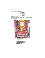
Page 19: ...board User s Guide Pin Signal 1 CD IN L 2 GND 3 GND 4 CD IN R Here is a list of CD_IN1 pin assignments Expansion Slots This motherboard has one PCI Express x16 one PCI Express x1 one CNR and two 32 bit PCI slots ...

Page 20: ...ated in the slot 4 Secure the metal bracket of the card to the system chassis with a screw PCI Express x16 Slot You can install an external PCI Express graphics card that is fully compliant to the PCI Express Base Specification revsion 1 0a PCI Express x1 Slot The two PCI Express x1 slots are fully compliant to the PCI Express Base Specifica tion revision 1 0a as well CNR Slot You can install the ...

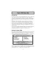
Page 21: ...re installed in or connected to the motherboard such as the CPU system memory disk drives etc Running the Setup Utility Every time you start your computer a message appears on the screen before the operating system loading that prompts you to Hit DEL if you want to run SETUP Whenever you see this message press the Delete key and the Main menu page of the Setup Utility appears on your monitor You c...

Page 22: ...d then fill in the hard disk characteristics Size Cyls etc manually If you have a CD ROM drive select the setting CDROM If you have an ATAPI device with removable media e g a ZIP drive or an LS 120 select Floptical FloppyA B These items set up size and capacity of the floppy diskette drive s installed in the system Some options on the main menu page lead to tables of items with installed values th...

Page 23: ...nactive at system start up time Boot to OS 2 64MB Enable this item if you are booting the OS 2 operating system and you have more than 64MB of system memory installed Aperture Size This item defines the size of aperture if you use a graphic adapter Auto detect DIMM PCI Clock When this item is enabled BIOS will disable the clock signal of free DIMM PCI slots CMOS Setup Utility Copyright C 1985 2005...

Page 24: ...t IRQ OnBoard PCI IDE Controller OnBoard PCI SATA Controller Onboard AC97 Audio DEVICE OnBoard AC97 Modem DEVICE Onboard LAN Device OnBoard LAN Boot ROM OnBoard USB Function USB Function For DOS OnBoard Floppy Controller Use this item to enable or disable the onboard floppy disk drive interface Serial Port1 Address Use this item to enable or disable the onboard COM1 2 serial port and to assign a p...

Page 25: ...oller OnboardAC97Audio DEVICE This item enables or disables the AC 97 audio chip OnBoard AC97 Modem Device This item enables or disables the onboard AC97 Modem device Onboard LAN Device This item enables or disables the onboard Ethernet LAN OnBoard LAN Boot ROM Enable this item if you want to execute the Boot ROM function of onboard LAN while starting the system OnBoard USB Function Enable this it...

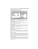
Page 26: ...ty the computer will enter power saving Suspend mode Resume On RTC Alarm The system can be turned off with a software command If you enable this item the system can automatically resume at a fixed time based on the system s RTC realtime clock Use the items below this one to set the date and time of the wake up alarm You must use an ATX power supply in order to use this feature Resume On KeyBoard T...

Page 27: ...CI slot Allocate IRQ to PCI VGA If this item is enabled an IRQ will be assigned to the PCI VGA graphics system You set this value to No to free up an IRQ PCI IDE BusMaster This item enables or disables the DMA under DOS mode We recommend you to leave this item at the default value PCI Plug and Play Setup Page This page sets up some parameters for devices installed on the PCI bus and those utilizin...

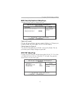
Page 28: ...to the items on this page BIOS Security Features Setup Page This page helps you install or change a password CMOS Setup Utility Copyright C 1985 2005 American Megatrends Inc CPU PnP Setup Help Item CPU Type AMD Athlon tm 64 Processor 3500 CPU OVERCLOCK 200 DIMM Voltage Adjust Function Normal CPU Voltage Control Disabled CMOS Setup Utility Copyright C 1985 2005 American Megatrends Inc BIOS Security...

Page 29: ... CMOS Setup Utility Copyright C 1985 2005 American Megatrends Inc Hardware Monitor Setup System Hardware Monitor Smart Fan Function Press Enter Vcore 1 360V NB Vcore 1 808V VDIMM 1 824V CPU FAN Speed 5720 RPM System Fan Speed 0 RPM CPU Temperature 27 C 80 F System Temperature 21 C 69 F Help Item Move Enter Select Value F10 Save Esc Exit F1 General Help F9 Optimized Defaults DIMM Voltage Adjust Fun...

Page 30: ... and Exit dialog box appears select OK to discard changes and exit or Cancel to return to the main menu Note If you have made settings that you do not want to save use the Discard Changes and Exit item and select OK to discard any changes you have made Load Optimal Defaults This option opens a dialog box to ask if you are sure to install optimized defaults or not You select OK and then Enter the S...

Page 31: ...o installing or manual installation depending on your operating system If your operating system is Windows 2000 XP it will automatically install all the drivers and utilities for your motherboard Installing Support Software 1 Insert the support CD ROM disc in the CD ROM drive 2 When you insert the CD ROM disc in the system CD ROM drive the CD automatically displays an Auto Setup screen 3 The scree...

Page 32: ...that this mainboard supports The ReadMe brings you to the Install Path where you can find out path names of software driver Auto Installing under Windows 98 2000 XP If you are under Windows 98 2000 XP please click the Setup button to run the software auto installing program while the Auto Setup screen pops out after inserting the support CD ROM 1 The installation program loads and displays the fol...

Page 33: ...tware you want to install 3 Follow onscreen instructions to install the software program step by step until finished AMI AWARD Flash Utility This utility lets you erase the system BIOS stored on a Flash Memory chip on the motherboard and lets you copy an updated version of the BIOS to the chip Proceed with caution when using this program If you erase the current BIOS and fail to write a new BIOS o...

Reviews: