background image


MANUAL #: 19179 
MANUAL REV: B 
ECO: 43785 


MODEL 482A21 LINE POWERED SIGNAL CONDITIONER


2


1.2 Introduction 


Model  482A21  is  a  single-channel,  line-operated  signal  conditioner  for  ICP

®

  transducer  systems.  This  unit  provides 

constant current excitation to the built-in transducer amplifier and decouples the signal from the DC bias voltage.  
 
The unit also contains provision for fault monitoring the channel, as well as provision for externally varying the constant 
current output over a 2 to 20 mA range. This model is factory set at 4 mA. 
 

2.0 Description 

 
Model 482A21 is powered externally by universal power supply model 488B04. The rear panel contains a BNC jack for 
transducer signal INPUT and a BNC jack for signal OUTPUT connections. 
 
The AC signal information is decoupled from the sensor bias by a coupling capacitor and brought out to the OUTPUT 
jack. 
 
The bias monitor located on the front panel consists of a color-coded panel meter that permanently monitors the sensor 
bias level. See sensor specification for correct sensor bias level. 
 

3.0 Installation


See  the  included  outline  drawing  for  dimensions,  as  well  as  jack  and  control  locations.  Plug  the  five-pin  DIN  output 
connector on 488B04 into the DC INPUT located on the rear panel of 482A21. 
 
Plug the three-wire line cord of the 488B04 into a source of 85 to 264 VAC, 47 to 440 Hz power and switch the power 
on for 482A21. 


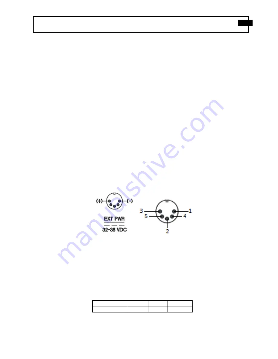
Pins 3 and 5 are (+) 

Pins 1, 2 and 4 are (-) 

Outside shell is earth/chassis ground 


Figure 1

: External Power Connector and Pin Numbers 

 
Note: For battery operation use model 488B07 in place of model 488B04. 
 
With no transducer connected to the INPUT connector, the front panel bias indicator meter indicates full scale (yellow), 
which corresponds to open circuit power supply voltage.  See Figure 2. 


Meter Reading 

Yellow 

Green 

Red 

Condition 

Open 

Ok 

Short 


Figure 2

: Fault Monitor Table 

Summary of Contents for 482A23/NP

Page 1: ...ne or DC Powered Installation and Operating Manual For assistance with the operation of this product contact PCB Piezotronics Inc Toll free 800 828 8840 24 hour SensorLine 716 684 0001 Fax 716 684 098...

Page 2: ...repair User servicing or repair is not recommended and if attempted may void the factory warranty Calibration Routine calibration of sensors and associated instrumentation is recommended as this helps...

Page 3: ...ry customer service representative Warranty All equipment and repair services provided by PCB Piezotronics Inc are covered by a limited warranty against defective material and workmanship for a period...

Page 4: ...isclosure Table Pb Hg Cd Cr VI PBB PBDE O O O O O O PCB X O O O O O O O O O O O X O O O O O O O O O O O O O O O O O O O O O O O O O X O O O O O O O O O X O O O O O O O O O O O X O O O O O X O O O O O...

Page 5: ...e O O X O O O Wires O O O O O O Cables X O O O O O Plastic O O O O O O Solder X O O O O O Copper Alloy Brass X O O O O O This table is prepared in accordance with the provisions of SJ T 11364 O Indica...

Page 6: ...grounded person The solution for product safety 1 Connect the cables only with the AC power off 2 Temporarily short the end of the cable before attaching it to any signal input or output Caution 2 ESD...

Page 7: ...ought out to the OUTPUT jack The bias monitor located on the front panel consists of a color coded panel meter that permanently monitors the sensor bias level See sensor specification for correct sens...

Page 8: ...tant current drive to the transducers 482A21 is normally supplied with the constant current output to the transducer set at 4 mA nominal This is adequate for most laboratory and field applications Spe...

Page 9: ...ative concerning the difficulty to ascertain if an on site procedure rectifies the problem If repair is indicated contact PCB to request a Return Materials Authorization RMA number from the factory An...

Page 10: ...select matches the channel of interest Output signal seems to drift Make sure the input impedance of the readout device scope or data acquisition system is approximately 1 M Low frequency response not...

Page 11: ......

Page 12: ...ght x Width x Length 6 3 in x 2 4 in x 11 in 16 cm x 6 1 cm x 28 cm Weight 1 51 lb 685 gm All specifications are at room temperature unless otherwise specified In the interest of constant product impr...

Page 13: ......

Reviews: