

PAGE 5
SENSO
RS AN
D INS
TRUME
N
TATI
O
N F
O
R MAC
HINE
CON
DITI
ON M
ON
IT
ORIN
G
Operation and Wiring
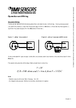
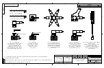
Standard Wiring
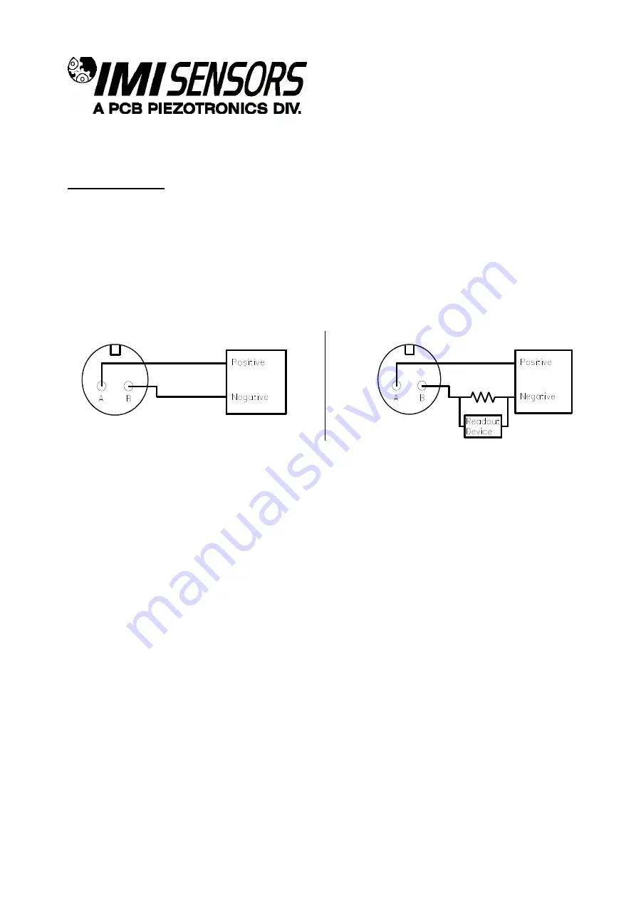
The Model 642/643/647/648 A Series operates from a standard 2-wire, 4-20mA loop. If using a loop powered
unit, attach the positive (+) input from the power supply to Pin A or
Red
wire on the sensor and the negative (-)
input from the power supply to Pin B or
Blue
wire of the sensor.
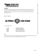
Figure 1
–
wiring: loop powered
Figure 2
–
wiring: loop powered/DC source
If using a standard DC power supply, install either an ammeter and/or load resistor in line with the output, Pin B or
Blue
wire.
The resistor will generate a DC voltage that is proportional to current by:
V
IR
If R
ohms and I
mA then V
VDC
500
6
3
,
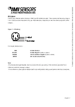
Note:
- Resistor value must be less than: (Vsupply
–
12) x 50.
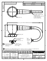
- For integral cable sensors: RED wire is positive, BLUE wire is negative.


