background image


PCB Load & Torque, Inc.   

 Toll-Free in USA 866-684-7107   

 716-684-0001   

 www.pcbloadtorque.com


DUAL BRIDGE LOAD CELL OPERATION MANUAL 


3


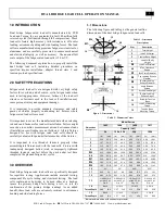
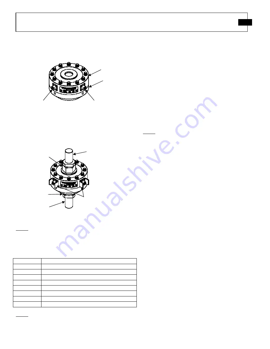
3.2 Standard Components 

The following figure describes the standard components of the 
dual bridge fatigue-rated load cells. 


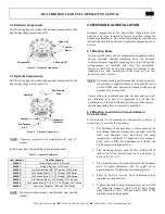
3.3 Optional Components 

The following figure describes the optional components of the 
dual bridge fatigue-rated load cells. 


NOTE:  Connector  protectors  are  standard  on  8”  and  11” 

models. 

 
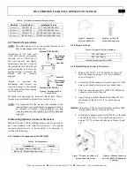
Table 3 describes the available optional components 


NOTE:  Pre-tension  studs  include  the  threaded  stud  and  the 

jam nut. 

4.0 MECHANICAL INSTALLATION 

 
Standard  components  of  the  dual  bridge  fatigue-rated  load 
cells  have  all  been  installed  to  factory  specified  values  for 
optimum performance.  The following mechanical installation 
instructions should be observed if optional components are to 
be used. 
 

4.1 Mounting Bases 

All low-profile load cells are calibrated and supplied with a 
factory  installed  standard  mounting  base.  An  optional 
custom (customer supplied) mounting base can, with special 
arrangements,  be  installed  and  used  for  calibration. 
However,  there  will  be  an  extra  charge  for  removal  of  the 
standard  base,  and  installation  of  the  load  cell  on  the 
customer’s base / fixture.  
 

NOTE:  To insure catalog performance specifications are met 

the customer’s supplied fixture or base must be flat to 
within  0.0002  inch  and  provide  similar  stiffness  and 
hardness to a factory base. 

 
Unless otherwise specified/requested, the base and load cell 
are  calibrated  as  a  unit.  It  is  important  to  note  that  the 
performance of the load cell may be affected if the  factory-
installed mounting base is removed or modified. 


4.2 Mounting Load Cell to a Standard Base or 
Custom Fixture 

If the load cell is to be mounted to a custom base or fixture, it 
is necessary to consider the following: 
 

1.


The thickness of the new base or fixture must not be 
any  thinner  than  the  original  base  supplied  with  the 
load  cell.  Materials  used  must  have  the  same 
temperature  coefficient  of  expansion  (for  example, 
4140  Steel  or  2024-T4  Aluminum  for  250,500  and 
1,000 capacity aluminum cells). 

 
2.


The  mounting  surface  must  be  flat  (within  0.0002 
inches),  and  steel  fixtures  must  have  a  hardness  of 
Rockwell C 33 to 37.  

 
3.


The  threaded  holes  and  under-head  of  the  fasteners 
must  be  lightly  lubricated  with  30  weight  oil  or 
equivalent prior to tightening the mounting bolts. 


4.


Refer  to  Table  4  for  the  final  tightening  torque 
required for each bolt size. 


5.


Tighten the bolts in an incremental cross pattern with 
the  following  sequence:  start  with  all  bolts  finger 
tight followed by 25%, 50% and finally 100% of the 
required torque being applied. 


Load Cell 

Tension 

Base 

Connector A 

Connector B 


Connector 

Protector 

Pre-Tension 

Stud 

Pre-Tension 

Stud 

Jam Nut 

Jam Nut 

Figure 2


– Standard Components 

Figure 3


– Optional Components 

Item Number 

Item Description 

084A40 

Lifting Rings (side), 1411 Series 

084A41 

Lifting Plug (top), 1411 Series 

084A55 

Pre-Tension Stud (5/8”-18 Thread), 1403 Series 

084A56 

Pre-Tension Stud (1 ¼”-12 Thread), 1404 Series 

084A57 

Pre-Tension Stud (1 ¾”-12 Thread), 1408 Series 

084A58 

Pre-Tension Stud (2 ¾”-8 Thread), 1411 Series  

084A59 

Pre-Tension Stud (2 ¾”-8 to 1 ¾”-12 Thread) 1411 Series 

084A90 

Connector Protector, 1403 and 1404 Series 


Table 3


– Optional Components 

Summary of Contents for 1404-03ADB

Page 1: ...DUAL BRIDGE Installation and Operating Manual For assistance with the operation of this product contact PCB Load Torque Inc Toll free 866 684 7107 24 hour SensorLine 716 684 0001 Fax 248 888 8266 E ma...

Page 2: ...alized tests including sensitivity at elevated or cryogenic temperatures phase response extended high or low frequency response extended range leak testing hydrostatic pressure testing and others For...

Page 3: ...tion on particular operating steps The following symbols may be found on the equipment described in this manual This symbol on the unit indicates that high voltage may be present Use standard safety p...

Page 4: ...China RoHS 2 Disclosure Table Pb Hg Cd Cr VI PBB PBDE O O O O O O PCB X O O O O O O O O O O O X O O O O O O O O O O O O O O O O O O O O O O O O O X O O O O O O O O O X O O O O O O O O O O O X O O O O...

Page 5: ...O Wires O O O O O O Cables X O O O O O Plastic O O O O O O Solder X O O O O O Copper Alloy Brass X O O O O O This table is prepared in accordance with the provisions of SJ T 11364 O Indicates that sai...

Page 6: ...LECTRICAL INSTALLATION 5 5 1 Electrical Drawing Western Regional Std 5 5 2 Cable Grounding Considerations 5 6 0 CALIBRATION 5 6 1 Calibration Certificate Description 5 6 1 1 Measured Output 6 6 1 2 Hy...

Page 7: ...the parts under test have completed the planned fatigue test cycles 3 0 OVERVIEW Dual bridge fatigue rated load cells are specifically designed for repetitive testing Applications include material te...

Page 8: ...ote that the performance of the load cell may be affected if the factory installed mounting base is removed or modified 4 2 Mounting Load Cell to a Standard Base or Custom Fixture If the load cell is...

Page 9: ...ctor Protector 1 Remove the 4 40 x 1 4 button head cap screws from the connector using a 1 16 hex wrench as shown in Figure 7 2 Carefully pull the connector from the load cell Take care to not break o...

Page 10: ...wiring may result in unstable or noisy signals A simple test with a voltmeter connected between the power cord ground and the structure on which the load cell is mounted can confirm that the structur...

Page 11: ...s are adjusted such that the error due to eccentric loading is less than 0 1 per inch of offset Side loads moments and torque must be limited to avoid electrical or mechanical damage to the load cell...

Page 12: ...tion certificate and adjust the span or gain until the display reads the force value stated on the certificate 4 Repeat steps 1 3 to verify that a valid calibration setting has been obtained 5 If poss...

Page 13: ...ridge resistances A D excitation and B C the signal leads 9 Check bridge balance 10 Keep a record of your observations correct problems or contact PCB factory for assistance 11 2 1 Estimating Bridge B...

Page 14: ...factory for any reason For calibration services if possible a copy of the purchase order covering the requested services should be included with the returned load cell 13 0 WARRANTY Standard warranty...

Page 15: ...8 90 mm 8 Weight 21 lb 9 53 kg Mounting Thread 1 1 4 12 UNF 3B No Metric Equivalent Sensing Element Strain Gage Strain Gage Mounting Torque 1400 in lb 158 Nm Deflection at Full Scale Capacity 0 001 in...

Page 16: ...BRIDGE 1 2 SUPPLIED WITH MATING FASTENERS WIRING CODE FOR T SERIES LOAD CELLS PIN A EXC PIN B SIG PIN C SIG PIN D EXC PIN E TEDS DATA PIN F TEDS GROUND 1204 M1204 1404 AND M1404 SERIES BASES n2 59 65...

Reviews: