PCB Arts GmbH
Instruction Manual Vapor Phase One
Page
18
of
27
SD Card/
├─
profiles/
│
├─
GC10.csv
│
├─
RTS.csv
│
├─
custom.csv
The SD card is automatically initialized during the boot process. If you insert or remove the
SD card during operation, press the Mount or Unmount button in the display first.
2.4
Attaching the temperature sensor
Place the temperature sensor close to your assembly so that the local temperature can be
measured as well as possible. The vapor phase is controlled to this temperature. This is the
blue line (actual temperature), which is shown in the display. The temperature sensor should
not have any thermal mass, otherwise the vapor phase control could start oscillating. Thread
the thermocouple through the grid once to prevent it from slipping during soldering and
place it at the correct height of the assembly. The sensor must be placed higher than the
highest component next to the assembly.
2.5
Creation of your own soldering profile
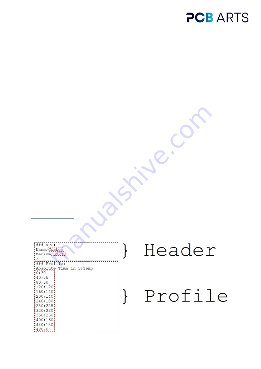
A soldering profile can be self-generated by following a CSV (Comma Separated Values)
format with semicolon "; " as separator. The absolute time in seconds and the corresponding
temperature in °C must always be specified. The soldering profile is structured as follows.
The fields marked in red can be changed. The profile may have a maximum length of 600
seconds. Example profiles are supplied initially or can be downloaded from our website
Always test new soldering profiles without a module so that you can
check whether it works as desired. Place the profile in the SD card in a folder with the name
"profiles".


