background image


PCB Arts GmbH 

Instruction Manual Vapor Phase One 

 Page 

21 

of 

27


In this case, a spring is attached to the temperature sensor leads. You can then carefully pull 
this over the tip of the temperature sensor that there is a safe thermal contact between 
thermocouple and heater.  
 

3.4


Installing software updates  

The Vapor Phase One will receive various software updates over time to constantly improve 
the operation but also the soldering results. For this purpose you will receive the current 
firmware on www.pcb-arts.com. There are three different files "VPO_DISP.BIN", 
"VPO_DISP_ASSETS.BIN" and "VPO_CORE.BIN", which you have to copy to a SD card in the 
root directory (without subfolders). You must then insert this SD card into the SD card slot of 
the vapor phase soldering system. 
 
  
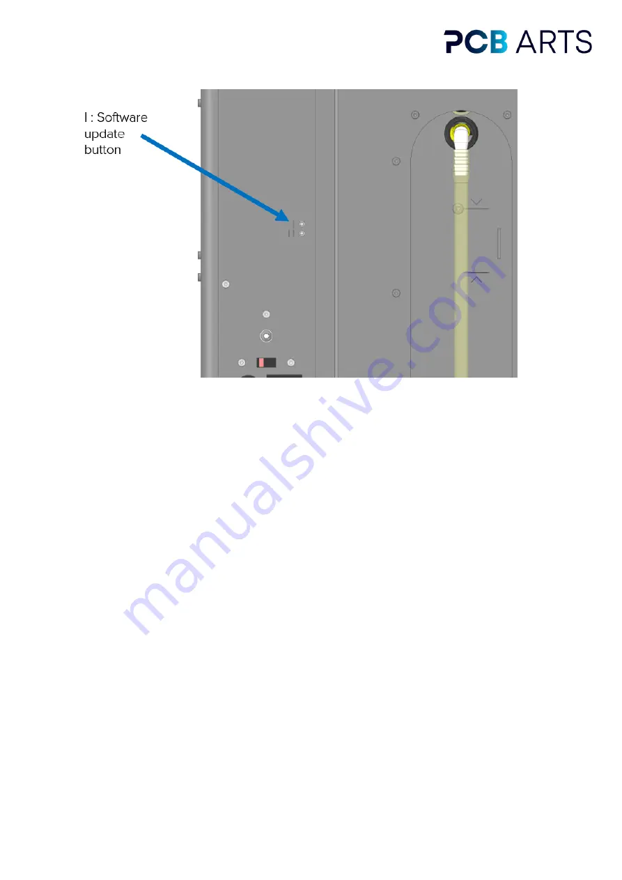
On the back of the vapor phase soldering unit you will find two buttons. Switch on the unit 
with the main switch while pressing the upper of these two buttons. 
 
This takes you to the bootloader of the Vapor Phase One (purple background). Confirm the 
update of the vapor phase soldering system once again with the upper button.  This starts 
the update, please do not switch off the device in this phase!  
 

Figure 10: Software update button


Summary of Contents for Vapor Phase

Page 1: ...ruction manual PCB Arts GmbH Kurgartenstraße 59 90762 Fürth DE Mail vpo pcb arts com https www pcb arts com Please read this manual before operating the Vapor Phase One and follow the instructions when operating Keep these instructions near the machine ...

Page 2: ...PCB Arts GmbH Instruction Manual Vapor Phase One Page 2 of 27 ...

Page 3: ... please do not hesitate to contact us at the e mail address given below The information in this document corresponds to the software version of delivery PCB Arts may make improvements and changes in this documentation and software at any time without notice For an up to date version visit our blog at www blog pcb arts com There you will also find tutorials tips tricks Enjoy using your new vapor ph...

Page 4: ... heating system 9 1 9 5 Limitation of steam ceiling height 9 1 9 6 Monitoring the cooling circuit temperature 9 1 9 7 Heating temperature monitoring 9 1 9 8 Monitoring the process chamber temperature 9 1 9 9 Trial Chamber 9 1 10 Cooling system 9 1 10 1 Initial filling of the vapor phase soldering system with distilled water 10 1 10 2 Draining the cooling medium 10 1 11 Damage in transit 10 1 11 1 ...

Page 5: ... Plant cannot be started 23 4 2 Heating does not work 23 4 3 Lid does not travel 23 4 4 Lift does not move 23 4 5 Profile does not start 23 4 6 Cooling water overtemperature 24 4 7 Oscillation of the ACTUAL temperature in the soldering profile 24 5 Operation tips 25 5 1 Soldering defects 25 5 1 1 Tombstone effect 25 5 1 2 Wicking effect 25 5 1 3 Solder beads 25 5 1 4 Solder paste does not melt 26 ...

Page 6: ... This vapor transports the energy of the heat source to the heat sink the assembly The vapor condenses first at the particularly cool points and thus releases the greatest amount of energy at these points In the vapor phase soldering system a specially developed inert medium is used which boils between 230 C and 240 C depending on the type of medium The condensing vapor gently heats the assembly t...

Page 7: ...e brand name Galden This is perfluoropolyether which is composed exclusively of carbon fluorine and oxygen atoms The advantages of Galden are Dielectric properties High material compatibility No flash point High heat transfer coefficient Not a hazardous substance in the sense of occupational health and safety 1 6 Footprint The Vapor Phase One must be set up with at least 20cm of protrusion all aro...

Page 8: ...ing views On the first operating view you will see the Open Lid button Press this button and the process lid opens automatically Now carefully fill the soldering medium into the process vat so that the filling quantity is between the minimum and maximum of the dipstick 1 8 Description of the plant The system is intended for reflow soldering of small quantities prototypes and individual pieces Cont...

Page 9: ...o limit the vapor ceiling height is monitored with a temperature sensor If the water temperature rises above X C X F the Vapor Phase One will not allow soldering 1 9 7 Heating temperature monitoring In addition to the correct dimensioning of the heating it is monitored and controlled by software Should the software control fail to function for inexplicable reasons dedicated evaluation electronics ...

Page 10: ...g with the vapor phase fill the water level to the maximum once again Repeat step 1 Water is also stored in the radiators which is why the water reservoir must be refilled after initial use 1 10 2 Draining the cooling medium To drain the water from the water reservoir you must pull the top end of the level hose off the plastic elbow and then drain it into a dedicated water container The distilled ...

Page 11: ... the discharge option For this purpose contact the manufacturer so that he can assist you with the correct emptying of the water reservoir For local transport of a few meters grab the vapor phase soldering system left and right from the bottom Since the vapor phase soldering system weighs about 25kg make sure that you carry the system with at least two people wearing protective work shoes Note tha...

Page 12: ...he circuit must be protected by a residual current device RCD A fuse holder is located above the cold appliance box in which two 10A carrying 230V fine wire fuses 5x20mm must be inserted In case of a short circuit check them and replace them if necessary If you use the vapor phase soldering system in 230V operation please set the voltage selector switch to 230V In case of 115V supply set the volta...

Page 13: ...9 5A 115V Inrush current typ 60A 230V Maximum power 1100W Dimensions 495mm x 318mm x 700mm W x D x H Weight approx 25Kg Process temperature 230 C 240 C Process cooling 4x fan Cooling Vapor phase limitation Water cooling Permissible ambient temperature 15 C 35 C In operation Permissible storage temperature 5 C 35 C Permissible humidity Max 70 non condensing 2 2 Part designations Figure 4 Front view...

Page 14: ...PCB Arts GmbH Instruction Manual Vapor Phase One Page 14 of 27 Figure 5 Rear view of vapor phase soldering system Figure 6 Top view of vapor phase soldering system ...

Page 15: ...le via the Start Reflow button 10 The assembly now moves in the process chamber on the basis of the soldering profile and live data is displayed every second in the graphic display 11 After the soldering profile is finished the Open Lid button remains grayed out until the Galden has reached the set Open Temperature in the Settings Page 12 You can now press Open Lid and remove the soldering materia...

Page 16: ...re units from C F Setting the opening temperature of the process chamber Selecting a soldering profile The following information is displayed on the touch panel The TARGET and ACTUAL soldering profile The warmest temperature of the cooling system The temperature of the soldering medium 2 3 2 Operation of the Vapor Phase One Open the process chamber by operating the touch panel You must press the O...

Page 17: ... from this moment on the Vapor Phase One operates completely autonomous and the soldering process starts Through the viewing window you can look into the process chamber and follow the soldering of your assembly After the solder profile is completed the Quick Cool of the Vapor Phase One switches on which ensures a faster cooling of the process chamber The board is then held at 120 C 248 F so that ...

Page 18: ...d the thermocouple through the grid once to prevent it from slipping during soldering and place it at the correct height of the assembly The sensor must be placed higher than the highest component next to the assembly 2 5 Creation of your own soldering profile A soldering profile can be self generated by following a CSV Comma Separated Values format with semicolon as separator The absolute time in...

Page 19: ...e assembly to this temperature During the profile You can now set the correct time in seconds and the desired temperature value behind it The vapor phase soldering system interpolates linearly between the temperature values to create a profile Spreadsheet programs with the functionality to display graphs such as Microsoft Excel are helpful for creating a profile Exit the profile The profile ends a...

Page 20: ...larly For this purpose you need suitable solvents such as isopropyl alcohol or methylated spirit never use aggressive cleaning agents First open the process chamber via the control panel and then switch off the vapor phase soldering system Be sure to also remove the power plug Always use a brush to clean the temperature sensors and clean them carefully Do not bend the temperature sensors or apply ...

Page 21: ...n www pcb arts com There are three different files VPO_DISP BIN VPO_DISP_ASSETS BIN and VPO_CORE BIN which you have to copy to a SD card in the root directory without subfolders You must then insert this SD card into the SD card slot of the vapor phase soldering system On the back of the vapor phase soldering unit you will find two buttons Switch on the unit with the main switch while pressing the...

Page 22: ...ase soldering system the button marked II is available for the self test When you press this the display will ask you if you want to perform a self test This takes about 5 minutes During this time all actuators are moved or switched on and an exact logging is performed The data is stored on the SD card The self test may only be performed when the vapor phase soldering system is initialized ...

Page 23: ...Undertemperature cooling system From 13 C 55 4 F the undertemperature shutdown of the vapor phase soldering system takes effect Please increase the temperature of the room Heating can not reach high temperatures Check that the voltage on the voltage selector switch is set correctly Thermocouple broken defective If it is visible that a thermocouple has become detached from the heaters please contac...

Page 24: ... 4 6 Cooling water overtemperature The cooling water temperature of the system is monitored at its hottest point here there is a hardware shutdown and a software shutdown The software shutdown prevents the start of a profile the hardware shutdown only takes effect in dangerous situations For example it can happen that during the soldering profile the overtemperature takes effect and the heating of...

Page 25: ...icient drying or incorrect storage Accordingly components can be thrown up 5 1 2 Wicking effect The wicking effect describes the rising of the molten solder on the component legs This does not result in a proper solder connection with the underlying connection pad The likelihood of this effect occurring can be minimized by the amount of solder paste the contact force when mounting the components a...

Page 26: ...d on the solder grid with spacers never place a double sided board directly on the solder grid The heavy components which have an unfavorable ground solder surface ratio should be fixed with SMD glue If the heavy components were already taken into account during layout creation and these were placed on the top side of the board gluing may not be necessary If your assembly allows it you can also as...

Page 27: ... unsigned software or if changes are made to the equipment setting values or accessories without the written consent of the manufacturer The warranty also expires if software is played on the Vapor Phase which does not originate from PCB Arts GmbH 6 2 Disclaimer We PCB Arts GmbH expressly declare that claims for damages are limited to the repair and the current market value of the vapor phase sold...

Reviews: