background image


Static Electricity Precautions 

Components on this mainboard can be damaged by static 
electricity. Take the following precautions when unpacking the 
mainboard and installing it in a system. 
1.  Keep the mainboard and other components in their original 

static-proof packaging until you are ready to install them. 

2.  During installation, wear a grounded wrist strap if possible. If 

you don’t have a wrist strap, discharge static electricity by 
touching the bare metal of the system chassis. 

3.  Handle the mainboard carefully by the edges. Avoid touching 

the components unless it is absolutely necessary. During 
installation put the mainboard on top of the static-protection 
packaging it came in with the component side facing up. 

Pre-Installation Inspection 

1.  Inspect the mainboard for damage to the components and 

connectors on the board. 

2.  If you suspect that the mainboard has been damaged, do not 

connect power to the system. Contact your mainboard vendor 
and report the damage.  


III

Summary of Contents for M935D

Page 1: ... right to revise this publication and to make changes from time to time in the content hereof without obligation of the manufacturer to notify any person of such revision or changes Trademarks IBM VGA and PS 2 are registered trademarks of International Business Machines Intel Pentium II III Pentium 4 Celeron and MMX are registered trademarks of Intel Corporation Microsoft MS DOS and Windows 98 ME ...

Page 2: ...inboard 12 Connecting Optional Devices 13 Install Other Devices 16 Expansion Slots 18 Chapter 3 BIOS Setup Utility 19 Introduction 19 Running the Setup Utility 20 Standard CMOS Setup Page 21 Advanced Setup Page 22 Power Management Setup Page 25 PCI Plug and Play Setup Page 27 Load Optimal Settings 28 Load Best Performance Settings 28 Features Setup Page 28 CPU PnP Setup Page 30 Hardware Monitor Pa...

Page 3: ...ave a wrist strap discharge static electricity by touching the bare metal of the system chassis 3 Handle the mainboard carefully by the edges Avoid touching the components unless it is absolutely necessary During installation put the mainboard on top of the static protection packaging it came in with the component side facing up Pre Installation Inspection 1 Inspect the mainboard for damage to the...

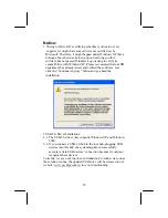
Page 4: ...dy tested and verified these drivers Just click the Continue Anyway button and go ahead the installation 2 USB 2 0 Driver Limitations 2 1 The USB 2 0 driver only supports Windows XP and Windows 2000 2 2 If you connect a USB 2 0 hub to the root hub plugging USB devices into this hub the system might not successfully execute certain USB devices connection because it could not recognize these devices...

Page 5: ...caractéristiques respectives NB SB Fonction SiS650GX SiS962L FSB533MHz Ultra DMA ATA133 DDR333 USB2 0 Support de Mémoire Deux logements DIMM 184 broches pour modules mémoire DDR 333 La mémoire maximum installée est 2Go Logements d Extension Un logement CNR Un logement 2x 4xAGP pour interface conforme AGP 2 0 Deux logements PCI 32 bits pour interface de bus conforme PCI 2 2 AC97 Audio Codec Conform...

Page 6: ...évision 2 0 Conforme aux Spécifications d interface de Contrôleur d Hôte Amélioré de Intel Révision 0 95 Conforme aux Spécifications d Interface de Contrôleur d Hôte Universel Révision 1 1 Le périphérique multifonction PCI consiste en deux noyaux de Contrôleur d Hôtes UHCI pour signalisation pleine faible vitesse et un noyau de Contrôleur d Hôtes EHCI pour signalisation haute vitesse Le hub racine...

Page 7: ...MHz Ultra DMA ATA133 DDR333 USB2 0 Speicherunters tützung Zwei 184 pin DIMM Steckplätze für DDR333Speichermodule Maximal auf 2GB Speicher erweiterbar Erweiterungsst eckplätze Ein CNR Steckplatz Ein 2x4xAGP Steckplatz für AGP 2 0 kompatibles Interface Zwei 32 Bit PCI Steckplätze für PCI 2 2 kompatibles Businterface AC97 Audio Codec Entspricht AC 97 2 2 16 Bit Stereo Vollduplex CODEC mit fixierter 4...

Page 8: ...n Revision 0 95 Entspricht Universal Host Controller Interface Spezifikation Revision 1 1 PCI Multifunktionsgerät besteht aus zwei UHCI Host Controller Kernen für Signalübertragung bei voller und niedriger Geschwindigkeit sowie einem EHCI Host Controller Kern für Hochgeschwindigkeits Signalübertragung Root Hub besteht aus 4 Downstream Ports mit integrierten Physical Layer Überträgern für gemeinsam...

Page 9: ...nstallabile 2GB Slot di espansione Una slot CNR Una slot AGP 2x4x per interfaccia AGP 2 0 compatibile Due slot PCI a 32 bit per interfaccia bus PCI 2 2 AC97 Audio Codec Conforme con le specifiche AC 97 2 2 CODEC 16 bit stereo full duplex con campionamento fisso a 48KHz 3 entrate analogiche con controllo del volume a 5 bit LINE IN CD IN AUX IN 2 CanDAC supporto di due uscite per le casse Gestione d...

Page 10: ...Compliant with Universal Host Controller Interface Specification Revision 1 1 PCI multi function device consists of two UHCI Host Controller cores for full low speed signaling and one EHCI Host Controller core for high speed signaling Root hub consists 4 downstream facing ports with integrated physical layer transceivers shared by UHCI and EHCI Host Controller Support PCI Bus Power Management Inte...

Page 11: ...rte de Memoria Dos ranuras 184 pin DIMM para módulos de memoria DR333 Memoria máxima instalada es 2GB Ranuras de Expansión Una ranura CNR Una ranura 2x 4xAGP para la interfaz conforme con AGP 2 0 Dos ranuras 32 bit PCI para la interfaz de bus conforme con PCI 2 2 AC97 Audio Codec Conforme con la especificación AC 97 2 2 CODEC de full duplex de estéreo 16 bit con índice de muestreo en 48KHz fijo 3 ...

Page 12: ...5 Conforme con la Especificación de Interfaz de Controlador Anfitrión Universal Revisión 1 1 Dispositivo PCI multi función se consiste de dos centros de Controlador Anfitrión UHCI para señalización de velocidad completa baja y un centro de Controlador Anfitrión EHCI para señalización de alta velocidaa Root hub consiste de 4 puertos que miran hacia abajo con transceptores de capa física integrado c...

Page 13: ...a DMA ATA133 DDR333 USB2 0 Suporte de memória Dois sockets DIMM com 184 pinos para módulos de memória DDR333 A memória máxima instalada é de 2GB Slots de expansão Um slot CNR Um slot AGP 2x 4x para uma interface compatível com AGP 2 0 Duas slots PCI de 32 bit para interface bus compatível com PCI 2 2 AC97 Audio Codec Compatível com a especificação AC 97 2 2 CODEC de 16 bits em duplex complete ster...

Page 14: ...o da interface Compatível com controlador Universal Host Revisão 1 1 da especificação da Interface O dispositivo PCI muli funções consiste em dois núcleos de Controlador UHCI Host Controller para sinalização de velocidade total baixa em um núcleo de Controlador EHCI Host para sinalização de alta velocidade O núcleo de raiz consiste em 4 portas de protecção a jusante com transreceptores de camadas ...

Page 15: ...iS962L FSB533MHz Ultra DMA ATA133 DDR333 USB2 0 内存支持 2 个用于 DDR333 内存条的 184 pin DIMM 插槽 内存最多可达 2GB 扩展槽 1 个 CNR 槽 1 个 2X 4XAGP 插槽 用于 AGP 2 0 兼容接口 2 个 32 位 PCI 插槽 用于 PCI 2 2 兼容总线接口 AC97 编解 码器 兼容 AC 97 2 2 规格 具有 48KHz 固定采样速率的 16 位全双工 CODEC 编解码器 3 路带 5 位音量控制的模拟线路电平立体声输入 LINE IN CD IN AUX IN 2 路 DAC 支持 2 路扬声器输出 电源管理 集成 I O 端 口 此主板具有完整的 I O 端口和插孔 2 个用于鼠标和键盘的 PS 2 端口 1 个串口 1 个并口 1 个 VGA 端口 4 个后面板 USB2 0 端...

Page 16: ...商 支持链路故障节电模式下操作 支持基线漂移 BLW 补偿 自适应均衡 USB 2 0 符合通用串行总线规格 2 0 版本 符合 Intel 0 95 版本的增强主控器接口规格 符合 1 1 版本的通用主控器接口规格 PCI 多功能设备由 2 个用于全速 低速传输 数据的 UHCI 主控器 和 1 个用于高速传输 数据的 EHCI 主控器组成 Root 集线器包括 4 个下行端口 带有与 UHCI 和 EHCI 主控制器 共用的集成物理层收发器 支持 1 1 版本的 PCI 总线电源管理接口规格 支持所有传统下行端口 部分硬件规格和软件项目若有更改恕不另行通知 XVI ...

Page 17: ... Video Accelerator and Advanced Hardware Acceleration MPEGI MPEGII Video Decoder for the Intel Pentium 4 series based PC systems It has the external AGP slot with AGP 4X 266MHz capability one CNR Communications and Networking Riser slot and built in 10BaseT 100BaseTX Network Interface optional In addition there is a full set of I O Ports including PS 2 keyboard and mouse ports one serial port one ...

Page 18: ...idge Function SiS650GX SiS962L CPU FSB 533MHz Ultra DMA ATA133 DDR333 USB2 0 Memory Support Two 184 pin DIMM sockets for DDR333 memory modules Maximum installed memory is 2GB Expansion Slots One CNR slot One 2x 4xAGP slot for AGP 2 0 compliant interface Two 32 bit PCI slots for PCI 2 2 compliant bus interface Onboard IDE channels Primary and Secondary PCI IDE channels Support for PIO programmable ...

Page 19: ...2 specification 16 bit stereo full duplex CODEC with fixed 48KHz sampling rate 3 analog line level stereo inputs with 5 bit volume control LINE IN CD IN AUX IN 2Ch DAC support 2 channel speak out Power management Built in Ethernet LAN optional Supports 10 100Mbps operation and half full duplex operation IEEE 802 3 802 3u compliant Supports IEEE 802 3u clause 28 auto negotiation Supports operation ...

Page 20: ...95 Compliant with Universal Host Controller Interface Specification Revision 1 1 PCI multi function device consists of two UHCI Host Controller cores for full low speed signaling and one EHCI Host Controller core for high speed signaling Root hub consists 4 downstream facing ports with integrated physical layer transceivers shared by UHCI and EHCI Host Controller Support PCI Bus Power Management I...

Page 21: ...ive ribbon cable Software support CD Optional Accessories You can purchase the following optional accessories for this mainboard Extended USB module CNR v 90 56K Fax Modem card Card Reader Note You can purchase your own optional accessories from the third party but please contact your local vendor on any issues of the specification and compatibility 5 ...

Page 22: ...all the mainboard in a system chassis case Connect any extension brackets or cables to connectors on the mainboard Install any peripheral devices and make the appropriate connections to connectors on the mainboard Note 1 Before installing this mainboard make sure jumper JP2 is under Normal setting See this chapter for information about locating JP2 and the setting options 2 Never connect power to ...

Page 23: ...Mainboard Components Use the diagram below to identify the major components on the mainboard Note Any jumpers on your mainboard not appearing in the illustration above are for testing only 7 ...

Page 24: ...connect serial devices such as mice or fax modems COM1 is identified by the system as COM1 VGA Use the VGA port to connect VGA devices LAN Port optional Connect an RJ 45 jack to the LAN port to connect your computer to the Network USB Ports Use the USB ports to connect USB devices Note The lower USB port located beside the VGA port is shared with the READ1 connector Audio Ports Use the three audio...

Page 25: ...478 CPUFAN 1 1 Unhook the locking lever of the CPU socket Pull the locking lever away from the socket and raising it to the upright position 2 Match the pin1 corner the beveled edge on the CPU with the pin1 corner on the socket shown as the above illustration Insert the CPU into the socket Do not use force 3 Push the locking lever down and hook it under the latch on the edge of socket 4 Apply ther...

Page 26: ... DIMMs can synchronously work with 100 MHz or 133 MHz memory bus DDR SDRAM provides 1 6 GB s or 2 1 GB s data transfer rate depending on whether the bus is 100 MHz or 133 MHz DDR SDRAM uses additional power and ground lines and requires 184 pin 2 5V unbuffered DIMM module DIMM1 DIMM2 Installation Procedure These modules can be installed with up to 2 GB system memory Following these steps to instal...

Page 27: ...ngs Using a jumper cap to connect two pins is SHORT removing it from these pins OPEN 1 JP2 Jumper JP2 Clear CMOS Memory This jumper can clear the contents of the CMOS memory You may need to clear the CMOS memory if the settings in the Setup Utility are incorrect and prevent your mainboard from operating To clear the CMOS memory disconnect all the power cables from the mainboard and then move the j...

Page 28: ...d internal mounting points on the chassis ATX2 1 SW1 CHSFAN 1 ATXPW1 Connect the power connector from the power supply to the ATXPW1 connector on the mainboard ATX2 is the CPU Vcore power connector If there is a cooling fan installed in the system chassis connect the cable from the cooling fan to the CHSFAN fan power connector on the mainboard Connect the case switches and indicator LEDs to the SW...

Page 29: ...e cable from the PC speaker to the SPK1 connector on the mainboard Pin Signal Pin Signal 1 SPKR 2 NC 3 GND 4 5V AUDIO2 Front Panel Audio Connector This connector allows the user to install auxiliary front oriented microphone and line out ports for easier access Pin Signal Pin Signal 1 AUD_MIC 2 AUD_GND 3 AUD_MIC 4 AUD_VCC 5 AUD_FPOUT 6 AUD_RET_R 7 NC 8 KEY 9 AUD_FPOUT 10 AUD_RET_L 13 ...

Page 30: ...d 2 Plug the bracket cable onto the JUSB1 connector 3 Remove a slot cover from one of the expansion slots on the system chassis Install an extension bracket in the opening Secure the extension bracket to the chassis with a screw READ1 USB Card Reader Connector optional This connector is for connecting internal USB card reader You can use a card reader to read or transfer files and digital images t...

Page 31: ...e purchased product IR1 Infrared Port The infrared port allows the wireless exchange of information between your computer and similarly equipped devices such as printers laptops Personal Digital Assistants PDAs and other computers Pin Signal Pin Signal 1 NC 2 KEY 3 5V 4 GND 5 IRTX 6 IRRX 1 Locate the infrared port IR1 connector on the mainboard 2 If you are adding an infrared port connect the ribb...

Page 32: ...e the cable provided to connect the drives to the floppy disk drive connector FLOPPY IDE Devices IDE devices include hard disk drives high density diskette drives and CD ROM or DVD ROM drives among others The mainboard ships with an IDE cable that can support one or two IDE devices If you connect two devices to a single cable you must configure one of the drives as Master and one of the drives as ...

Page 33: ...the mainboard If you have two devices on the cable one must be Master and one must be Slave Internal Sound Connections If you have installed a CD ROM drive or DVD ROM drive you can connect the drive audio cable to the onboard sound system CD1 1 When you first start up your system the BIOS should automatically detect your CD ROM DVD drive If it doesn t enter the Setup Utility and configure the CD R...

Page 34: ... CNR PCI expansion card 1 Locate the AGP CNR or PCI slots on the mainboard 2 Remove the blanking plate of the slot from the system chassis 3 Install the edge connector of the expansion card into the slot Ensure the edge connector is correctly seated in the slot 4 Secure the metal bracket of the card to the system chassis with a screw 18 ...

Page 35: ...ordination between system components If the Setup Utility configuration is incorrect it may cause the system to malfunction It can even stop your computer from booting properly If this happens you can use the clear CMOS jumper to clear the CMOS memory used to store the configuration information You can run the setup utility and manually make changes to the configuration You might need to do this t...

Page 36: ...k type etc You can use the cursor arrow keys to highlight any of the options on the main menu page Press Enter to select the highlighted option To leave the setup utility press the Escape key To cycle through the Setup Utility s optional color schemes hold down the Shift key and press F2 Some of the options on the main menu page lead to tables of items with installed values In these pages use the ...

Page 37: ...ec Slave Auto On Floppy Drive A 1 44 MB 3 1 2 Floppy Drive B Not Installed Month Jan Dec ESC Exit Day 01 31 Select Item Year 1901 2099 PU PD Modify Shift F2 Color F3 Detect All HDD Date Time Use these items to set the system date and time Pri Master Pri Slave Sec Master Sec Slave Use these items to configure devices connected to the Primary and Secondary IDE channels To configure an IDE hard disk ...

Page 38: ...R T for Hard Disks Disabled BootUp Num Lock On Floppy Drive Swap Disabled Floppy Drive Seek Disabled Password Check Setup Boot To OS 2 64MB No L2 Cache Enabled System BIOS Cacheable Disabled Share Memory Size 32 MB Graphic Win Size 4MB DRAM CAS Latency 3T Timing Setting Mode Normal MA 1T 2T Select MA 2T Advanced Read Prefetch Enabled Hyper Threading Function Disabled ESC Quit Select Item F1 Help P...

Page 39: ...item drive A becomes drive B and drive B becomes drive A Floppy Drive Seek If you enable this item your system will check all floppy disk drives at start up Disable this item unless you are using an old 360KB drive Password Check If you have entered a password for the system use this item to determine if the password is required to enter the Setup Utility Setup or required both at start up and to ...

Page 40: ...at the default value The 3T setting requires faster memory that specifically supports this mode Timing Setting Mode This item determines the timing setting mode of the memory We recommend you leave this item at the default value MA 1T 2T Select This item adjusts timing 1T 2T latency We recommend you to leave this item at the default value Advanced Read Prefetch This item enables prefetching for re...

Page 41: ...up Page This page sets some of the parameters for system power management operation AMIBIOS SETUP POWER MANAGEMENT SETUP C 2000 American Megatrends Inc All Rights Reserved ACPI Aware O S Yes Power Management Enabled Suspend Time out Disabled Hard Disk Time out Disabled Resume On RTC Alarm Disabled RTC Alarm Date 15 RTC Alarm Hour 12 RTC Alarm Minute 30 RTC Alarm Second 30 LAN Ring Power On Disable...

Page 42: ...f you enable this item the system can automatically resume at a fixed time based on the system s RTC realtime clock Use the items below this one to set the date and time of the wake up alarm You must use an ATX power supply in order to use this feature LAN Ring Power On The system can be turned off with a software command If you enable this item the system can automatically resume if there is an i...

Page 43: ...ts F7 Load Setup Defaults Plug and Play Aware O S Enable this item if you are using an O S that supports Plug and Play such as Windows 95 98 ME Primary Graphics Adapter This item indicates if the primary graphics adapter uses the PCI or the AGP bus The default PCI setting still lets the onboard display work and allows the use of a second display card installed in a PCI slot Allocate IRQ to PCI VGA...

Page 44: ...alues These default values are quite demanding and your system might not function properly if you are using slower memory chips or other low performance components Features Setup Page This page sets some of the parameters for peripheral devices connected to the system AMIBIOS SETUP FEATURES SETUP C 2000 American Megatrends Inc All Rights Reserved OnBoard FDC Enabled OnBoard Serial Port 3F8h COM1 O...

Page 45: ...l port mode You can select SPP Standard Parallel Port ECP Extended Capabilities Port EPP Enhanced Parallel Port or ECP EPP Parallel Port IRQ Use this item to assign either IRQ 5 or 7 to the parallel port Parallel Port DMA Use this item to assign a DMA channel to the parallel port The options are 0 1 and 3 Onboard PCI IDE Use this item to enable or disable either or both of the onboard Primary and ...

Page 46: ...00 American Megatrends Inc All Rights Reserved CPU Type Intel P4 Auto Detect CPU DRAM Freq Enabled CPU DRAM Speed 100 100 MHz CPU Core Voltage 1 728V CPU Ratio H W TRAP CPU Frequency 100 MHz DRAM Frequency 100 MHz ESC Quit Select Item F1 Help PU PD Modify F5 Old Values Shift F2 Color F6 Load Optimal values F7 Load Best performance values CPU Type Core Voltage Ratio Frequency These items show the t...

Page 47: ...Shift F2 Color F6 Load BIOS Defaults F7 Load Setup Defaults System CPU Temperature These items display Power CPU and System temperature measurement FANs Voltage Measurements These items indicate cooling fan speeds in RPM and the various system voltage measurements Change Password If you highlight this item and press Enter a dialog box appears which lets you enter a Supervisor password You can ente...

Page 48: ...he current password At the next dialog box type in the new password or just press Enter to disable password protection Exit Highlight this item and press Enter to save the changes that you have made in the Setup Utility configuration and exit the program When the Save and Exit dialog box appears press Y to save and exit or press N to exit without saving 32 ...

Page 49: ...in the same directory as the software To run the support CD simply insert the CD into your CD ROM drive An Auto Setup screen automatically pops out and then you can go on the auto installing or manual installation depending on your operating system If your operating system is Windows 98 ME 2000 XP it will automatically install all the drivers and utilities for your mainboard if Windows NT or manua...

Page 50: ...the software auto installing program as explained in next section The Browse CD button is a standard Windows command that you can check the contents of the disc with the Windows 98 file browsing interface The Exit button closes the Auto Setup window To run the program again reinsert the CD ROM disc in the drive or click the CD ROM driver from the Windows Explorer and click the Setup icon The Appli...

Page 51: ...the items that you want to setup by clicking on it the default options are recommended Click the Next button to proceed 3 The support software will automatically install Once any of the installation procedures start software is automatically installed in sequence You need to follow the onscreen instructions confirm commands and allow the computer to restart as few times as needed to complete insta...

Page 52: ... Find out your mainboard model name and click on it to obtain its correct driver directory 3 Install each software in accordance with the corresponding driver path Bundled Software Installation All bundled software available on the CD ROM is for users convenience You can install bundled software as follows 1 Click the Application button while the Auto Setup screen pops out after inserting the supp...

Reviews: