11
3. USE
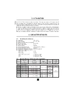
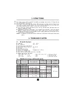
Limit the measuring time between 1000 and 1200 A : 15 minutes on, followed by 30 minutes off.
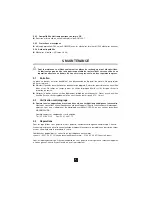
With the C100 model, which is not protected by an output limiter, do not clamp a conductor before
connecting the clamp to the corresponding measuring device. Likewise, do not disconnect the clamp
from the measuring appliance when the clamp is still attached to the cable.
n
Before connecting the clamp to the multimeter, check that the multimeter has an appropriate calibre.
n
Open the jaws and clamp the cable through which the current you wish to measure is running.
Roughly centre the cable in the jaws. Follow the direction of the arrow, if so required by the
application in question.
n
To read the measurement, apply the appropriate reading coefficient (See 4.2 “Input/output ratio”).
NB :
for multi-calibre models, select the ratio which provides the best resolution and precision.
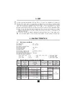
4. CHARACTERISTICS
4.1
Reference conditions
n
Temperature
: +20... +26°C
n
Humidity
: 20... 75% RH
n
Conductor centred in jaws
n
Sinusoidal current
: 48... 65 Hz
n
Distortion factor
: < 1%
n
Direct current
: no
n
Continuous magnetic field
: earth field (< 40 A/m).
n
Alternating magnetic field
: no
n
Proximity of external conductors : no current
n
Measuring device impedance
- C100 / C102 / C103 :
≤
5
Ω
- C106 / C107 / C116 / C117 :
≥
1 M
Ω
and
≤
100 pF
- C112 / 113
:
≤
1
Ω
- C160
:
≥
1 M
Ω
and
≤
47 pF
- C122 / C148
:
≤
0.2
Ω
- C173
:
≥
10 M
Ω
and
≤
100 pF
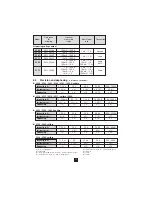
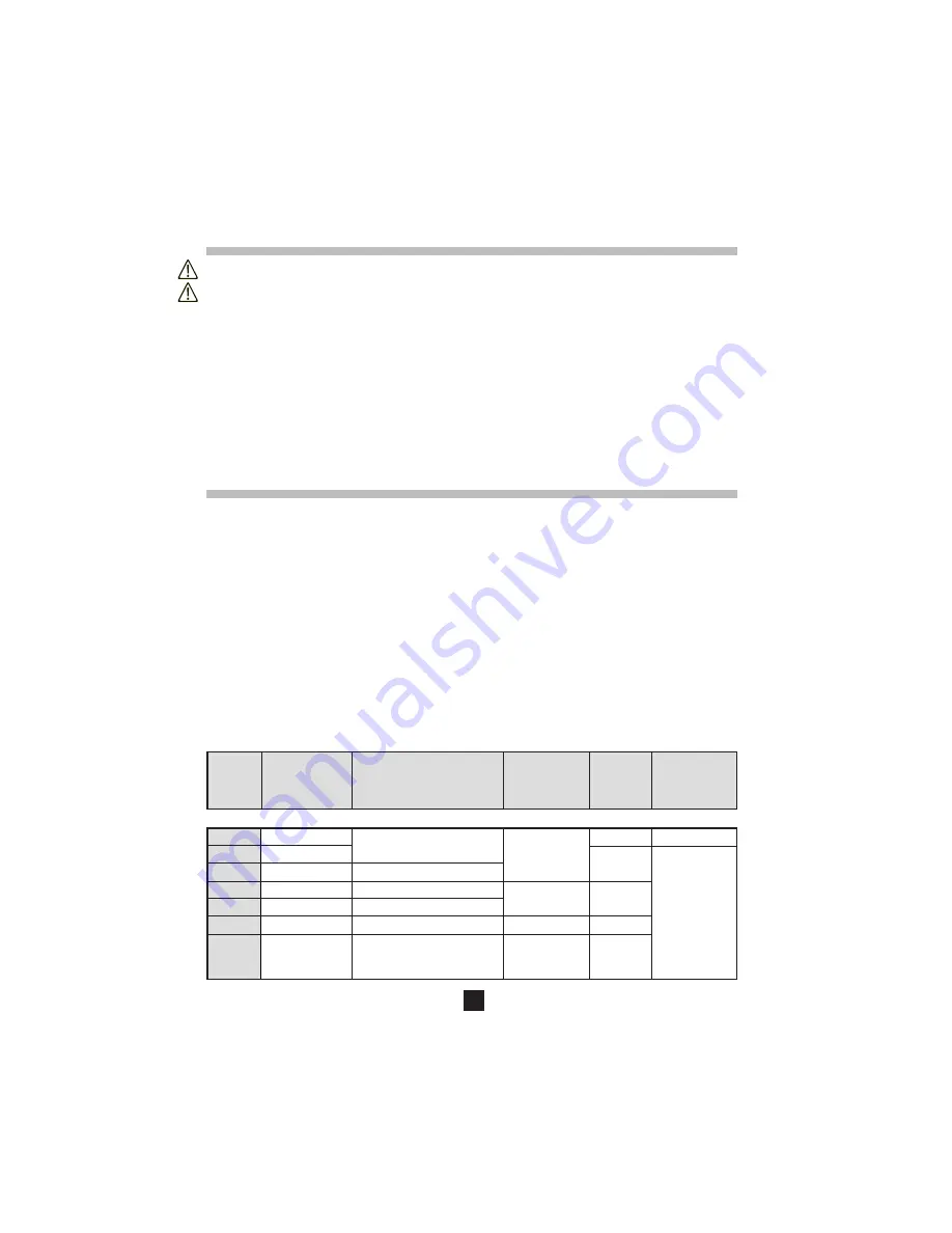
4.2
Specifications and references for ordering
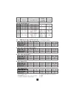
Reference
Nominal
Ouput
Model
for
measuring
Input/Ouput
Connec-
protected
ordering
scope
ratio
tion
against
voltage surges
Alternating current output
C100
P01.1203.01
100 mA... 1000 A
Sockets
No
C102
P01.1203.02
1 mA~ / 1 A~
Sockets
C112
P01.1203.14
10 mA... 1000 A
C103
P01.1203.03
100 mA... 1000 A
1 mA~ / 1 A~
Leads
30 V
C113
P01.1203.15
10 mA... 1000 A
max. peak
C122
P01.1203.06
1 A... 1000 A
5 mA~ / 1 A~
Sockets
5 mA~ / 1 A~
C148
P01.1203.07
1 A... 1000 A
10 mA~ / 1 A~
Sockets
20 mA~ / 1 A~


