background image

TABLE OF CONTENTS

1. FEATURES.................................................................1

2. SPECIFICATIONS.......................................................1

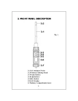
3. FRONT PANEL DESCRIPTION..................................... 3

3-1 Soil moisture Probe..............................................3

3-2 Moisture Sensing Head.........................................3

3-3 Power Button...................................................... 3

3-4 Hold Button.........................................................3

3-5 REC Button..........................................................3

3-6 LCD Display.........................................................3

3-7 Battery Compartment/Cover.................................3

4. MEASURING PROCEDURE..........................................4

4-1 Measurement by selecting the different

        material............................................................4

4-2 Data Hold............................................................5

4-3 Data Record........................................................5

5. BATTERY REPLACEMENT...........................................6

Summary of Contents for PCE-SMM 1

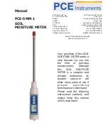
Page 1: ...niques are developed Please read the following instructions carefully and always keep this manual within easy reach PCE Americas Inc 711 Commerce Way Suite 8 Jupiter FL 33458 USA From outside US 1 Tel...

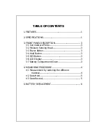
Page 2: ...moisture Probe 3 3 2 Moisture Sensing Head 3 3 3 Power Button 3 3 4 Hold Button 3 3 5 REC Button 3 3 6 LCD Display 3 3 7 Battery Compartment Cover 3 4 MEASURING PROCEDURE 4 4 1 Measurement by selecti...

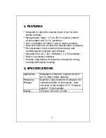
Page 3: ...accuracy and provides special functions and features Operates from DC 1 5V UM4 AAA x 4 PCs batteries Built in low battery indicator Durable long lasting components enclosed in strong compact ABS plas...

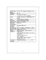
Page 4: ...display reading Sampling Time Approx 0 8 second Operating 0 to 50 Temperature Operating Less than 80 R H Humidity Power Supply DC 1 5 V battery UM4 AAA x 4 PCs Power Current Approx DC 12 mA Weight 267...

Page 5: ...3 FRONT PANEL DESCRIPTION Fig 1 3 1 Soil moisture Probe 3 2 Moisture Sensing Head 3 3 Power Button 3 4 Hold Button 3 5 REC Button 3 6 LCD Display 3 7 Battery Compartment Cover 3...

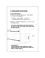
Page 6: ...urn off the meter 2 Insert the Moisture sensing head 3 2 Fig 1 into the measured soil It is recommended that probe head should be inserted into the soil at least 10 cm when make the measurement Soil m...

Page 7: ...th the REC symbol on the display a Press the REC Button 3 5 Fig 1 momentarily the REC MAX symbol along with the maximum value will appear on the display b Press the REC Button 3 5 Fig 1 momentarily ag...

Page 8: ...eft corner of the LCD displays the low battery icon using 4 fresh 1 5 V UM4 AAA batteries To change the batteries open rotate clockwise direction the Battery Cover 3 7 Fig 1 Make sure the Battery cove...

Reviews: