background image

5.1 Connecting the sensor

a. Note that this meter accepts only the supplied vibration sensor.

b. Plug the connector side of the sensor into the plug at the top of the meter.

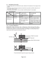
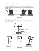
c. The sensor can be connected to the machinery under test in three ways.

Please refer the blow.

5.2  Power ON-OFF

a. Press the POWER button to turn the meter ON or OFF.

b. The meter is equipped with an automatic power off utility that conserves 

battery life. If the meter is left inactive for 30 minutes it will automatically turn 

off. The automatic power off utility is enabled or disabled by pressing and hold 

the volume key for 5s. The symbol ‘SV’ showing on the display indicates auto 

power off utility is enabled. Otherwise, disabled if not showing ‘SV’.

5.3  How to set coordinate axis

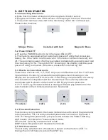
There are 4 choices of X, Y, Z, XYZ. Any one coordinate axis of X or Y or Z with 

3 parameters of velocity, acceleration and displacement showing on one 

display can be selected. Or 3-axis of X-Y-Z with any one parameter of velocity 

or acceleration or displacement can be selected. The currently selected 

coordinate axis is shown on the meter’s LCD. Every time to press the 

X / Y/ Z / XYZ key, the selected axis is changed. Please pay attention to the 

axes marked on the 3 dimensional sensor. See below. 

5.  GETTING STARTED

Front ( A )

Z ( C )

X ( B ) 

Y ( D )  

5.4  Function Selection

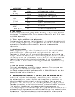
Function key is only valid in the 3-axis mode and used to select the parameter 

to be measured. The currently selected parameter is shown on the meter’s

LCD. To change the parameter, just press and release the FUNCTION key.

ACC means  ‘Acceleration’ measurement mode.

VEL means  ‘Velocity’ measurement mode.

DISP means ‘Displacement’ measurement mode.

5.5  Unit Conversion

The currently selected unit of measure is shown on the meter’s LCD. To 

change the unit of measure, press the UNIT key.   

Stinger Probe 

Installed with bolt

Magnetic Base   

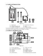
Summary of Contents for PCE-VM 3D

Page 1: ...de US 1 Tel 561 320 9162 Fax 561 320 9176 info pce americas com www pce instruments com english www pce instruments com PCE Instruments UK Ltd Units 12 13 Southpoint Business Park Ensign way Hampshire...

Page 2: ...sor 1pc Stinger probe Cone 1pc Stinger probe Ball 1pc Carrying case 1pc Operational instruction manual 1pc Optional Accessories Headphones for use as electronic stethoscope Cable for RS232C or USB Blu...

Page 3: ...6 Magnetic Base 3 1 Main Body 3 2 Stinger Probe Cone 3 3 Stinger Probe Ball X Y Z 3D VIB R ATIO N SEN SO R 3 1 3 2 3 3 3 4 3 5 3 6 4 1 3 axis indication 4 2 Low battery indication 4 3 Z axis 4 4 Veloc...

Page 4: ...n on the result Cost Convenience 4 2 1 Installed With Bolt Application range Screw eye has no influence on the running of the object being tested Usage Drill a screw eye 5mm deep in the object being t...

Page 5: ...distortion The mass istoo small Forming bevel between the needle and the surface 4 2 2 Installed With Magnetic Base Figure 4 3 Application range Magnetic flat surface roughness less than Ra1 6 accele...

Page 6: ...X or Y or Z with 3 parameters of velocity acceleration and displacement showing on one display can be selected Or 3 axis of X Y Z with any one parameter of velocity or acceleration or displacement can...

Page 7: ...5 9 RS 232 Serial PC Interface The meter is equipped with an RS 232 serial data port This interface was designed to operate with enables the user to capture store and display readings on a PC USB and...

Page 8: ...delines for acceptable vibration levels of machinery in different power categories See Appendix Acceleration has excellent high frequency measurement capabilities and is therefore very effective for d...

Page 9: ...rection V vertical direction Please define A H V as X Y Z axes respectively Angle Always perpendicular to the surface 90 10 Pressure Even consistent hand pressure must be used firm but not so firm as...

Page 10: ...according as vibration velocity Quality rank Rev rpm Normal Good R Excellent S 600 3600 600 1800 1800 3600 600 1800 1800 3600 H high of shaft mm Maximum vibration velocity rms mm s 80 H 132 4 5 1 8 2...

Page 11: ...r fault liquid force mechanical loose reciprocating force fs 1 x N x N is the tooth number of the fault gear 2 x N x N is the paddle number of the fault pump or fan fs fs fs fs N multiple of fs 1 Driv...

Reviews: