Manual
6
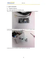
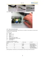
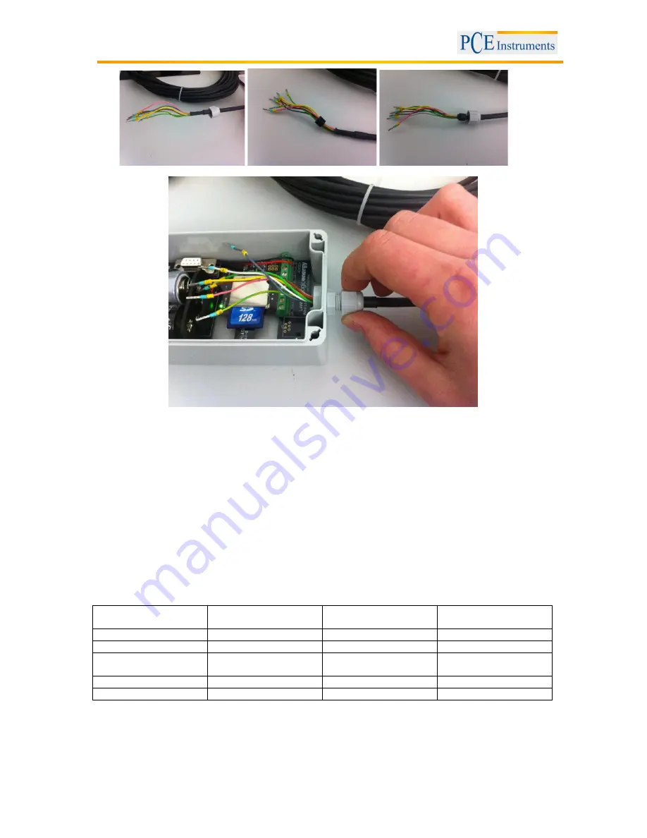
Now you can insert the cable into the case through the gland and fix the nut.
4.1.2
How to connect the sensor
The connector block of the sensors is fixed to the main circuit board. The connectors on the main circuit
board have the following functions:
From left to right:
G:
ground
A2:
input of sensor 2
G:
ground
A1:
input of sensor 1
G:
ground
D:
input of wind direction sensor
D+:
power supply of wind direction sensor
V+:
positive pole (red)
G:
ground (black)
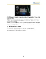
The sensor is connected as follows:
Connection to circuit
board
Cable marker
Cable colour
Function
A1
1
white
input of sensor 1
G
2
brown
ground of sensor 1
D+
6
pink
power supply of wind
direction sensor
D
5
grey
input wind direction
G
4
yellow
ground wind direction
When everything is connected, the circuit board and the connector block should look like this:

