GRL-PCIE5-CEM-RXA User Guide and MOI
Rev7.0
© Granite River Labs 2022 Version 7.0, June 2022. Updated 06.29.2022
Page 100 of 123
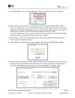
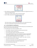
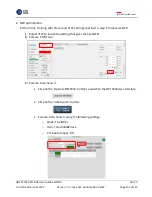
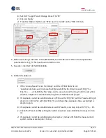
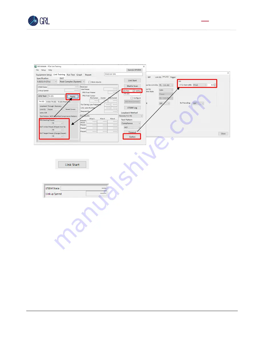
ii)
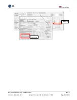
Set
‘
DUT Initial Preset (Preset Hint Tx)
’
to
‘
P9
’
iii)
Set
‘
DUT Target Preset (Change Preset)
’
to
‘
P9
’
iv)
Click on
‘
Apply
’
v)
From the
‘
Option
’
button, set
‘
CTLE Gain
’
to
‘
0.0 dB
’
on the
‘
PPG / ED
’
tab.
4.
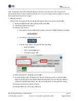
Execute
‘
Link Start
’
of MX183000A.
5.
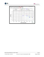
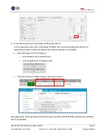
Establish Loopback.
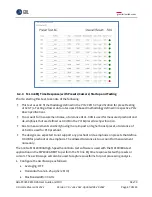
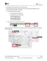
i)
If
the ‘
Linkup Speed
’
is not
‘
32.0 Gbps
’
and the
‘
LTSSM State
’
is not
‘
Loopback.Active.Lead
’
, reduce the CTLE setting of step 3 v) by 3 dB, re-execute Link
Training, and confirm whether Loopback is established through the LTSSM State
displayed.
ii)
If Loopback cannot be established even if CTLE is set to -12 dB, set the Preset setting of
steps 3 ii) / 3 iii) to
‘
P8
’
, set CTLE to
‘
0 dB
’
, and check the Loopback status according to
step 5 i).
iii)
If Loopback cannot be established even with Preset P8, redo step 5 ii) with P7, P6, ... P0.
iv)
Check the Preset and CTLE settings for which Loopback was established in steps 5 i) to
5 iii).
v)
If Loopback cannot be established up to step 5 iv), remove ISI from the measurement
system and execute steps 5 i) to 5 iv).
Note: If Loopback cannot be established by the procedure up to this point, the measurement
environment may be incorrect (cable connection error, etc.) or it may be a DUT problem, so review
the measurement environment again.

