GRL-PCIE5-CEM-RXA User Guide and MOI
Rev7.0
© Granite River Labs 2022 Version 7.0, June 2022. Updated 06.29.2022
Page 93 of 123
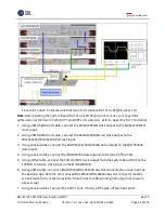
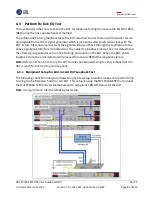
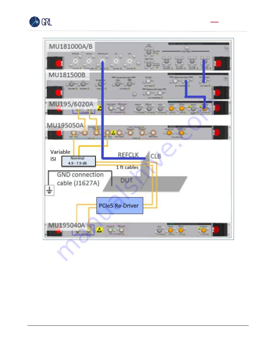
F
IGURE
56.
C
ONNECTION
D
IAGRAM FOR
PCI
E
G
EN
5
S
YSTEM
B
OARD
DUT
L
OOPBACK
T
EST
Note
: Before starting the System Board DUT Loopback Test, make sure to perform optimization of
the Return Path (DUT Tx to BERT error detector). Refer to Appendix B or C for details.
1.
Using a SMA-SMA short cable, connect the MU181000A/B clock output to the MU181500B Ext
clock input.
2.
Using a SMA-SMA short cable, connect the MU181500B jittered clock output to the
MU195020A/MU196020A Ext clock input.
3.
Using coaxial cables, connect the MU195020A/MU196020A data outputs to the MU195050A
data inputs.
4.
Using coaxial cables, connect the MU195050A data outputs to the Variable ISI (Nominal 4.9
–
7.9 dB).

