background image

76411 Issue 2 

www.pclairtechnology.com 

NEXUS Generator & Multi-head Inflator 

User Manual


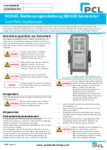
Safety Guidelines 

This manual contains information that is very important to know 
and understand. This information is provided for safety and to 
prevent equipment problems. To help recognise this information, 
observe the following symbols. 
 

Danger indicates an imminently hazardous 
situation which if not avoided WILL result 
in death or serious injury. 


Warning indicates a potentially hazardous 
situation which if not avoided, COULD 
result in death or serious injury. 


Caution indicates a potentially minor or 
moderate injury. 


Notice indicates important information, 
that if not followed, may cause damage to 
equipment. 


Unpacking 

After unpacking the unit, inspect carefully for any damage that 
may have occurred during transit. 
 

Do not operate unit if damaged during 
shipping, handling or use. 


General Safety Information 

The operator of this product must take the necessary precautions 
to prevent the level of danger indicated by these symbols. The 
operator is required to read and understand this instruction 
manual and all safety warnings, labels etc. 
 
Any employer allowing the use of this product in their field of work 
must distribute this instruction manual to all users. The employer 
must also ensure all users read, understand and follow the 
instructions as described in the manual, safety warnings, labels, 
etc. 
 

Please read and save these instructions. Read carefully before attempting to assemble, install, operate or maintain the product described. 
Protect yourself and others by observing all safety information. Failure to comply with instructions could result in personal injury and/or 
property damage! Retain instructions for future reference.  

Image shown is PCL standard decal. 

Actual decal may vary by individual part number. 

Read and understand all safety warnings 
and instructions before operating this 
product. Failure to read and follow all 
safety warnings may result in serious 
personnel injury or death. Property 
damage and/or product damage may also 
occur if all warnings are not followed.  


1. 

Do not expose the product to flammable gases, 
vapours or fumes 

2. 

Do not store flammable gases in or near this product 

3. 

Never use flammable or toxic solvents to clean the 
product or any of the unit's parts 

4. 

Never remove or alter any safety warning labels, tags, 
etc. located or provided with product. 

5. 

Follow all directions for maintenance. 


The use of other than genuine PCL 
replacement parts may result in reduced 
equipment performance. Repairs must be 
performed by authorised repair personnel, 
otherwise the warranty will be void. 

PART NUMBER 


SERIAL NUMBER 


Summary of Contents for NEX2/MQ

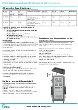
Page 1: ...is instruction manual to all users The employer must also ensure all users read understand and follow the instructions as described in the manual safety warnings labels etc Please read and save these...

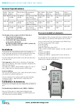
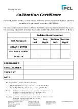
Page 2: ...ximum permissible error MPE 0 08 bar Each unit before release is checked and calibrated on test equipment that has accuracy traceable to a UKAS Laboratory No 0221 referenced to certificate 0029346 NEX...

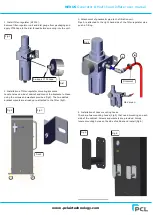
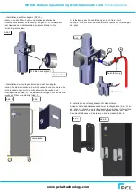
Page 3: ...screws and washers provided fig2 The two slotted bracket mounts are already pre attached to the filter fig3 3 Attachment of pneumatic pipe to the filtration unit Pipe A is attached to the right hand s...

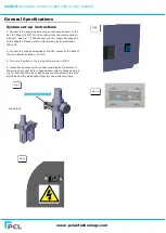
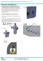
Page 4: ...to the adaptor Please note the N6 version has a combination filter unit 2 Connect the mains power lead to the IEC socket at the back of the unit cabinet as shown in FIG 8 3 Turn on off switch to the o...

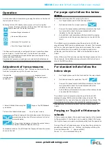
Page 5: ...3 Connect the hoses marked with Blue indicator to the front two tyres and connect the hoses marked with white indicator to the rear two tyres 4 Auto deflation will commence with the default 2 purging...

Page 6: ...d 5 cycles increase cycles to improve N2 tyre purity On N6 models ONLY when the desired inflation pressure is above 60psi 4 1bar you only require 1 purge as standard to achieve an acceptable purity le...

Page 7: ...your region or country The unit is designed and built to the relevant basic health and safety requirements of the EC This product can be dangerous if used improperly Children should not be allowed to...

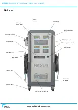
Page 8: ...om Filter regulator unit LCD Display Valve cap tray Hose hooks Output hose connections 4 individual exhausts 90mm castors Rear tyres control panel On Off switch Auxiliary port N2 Tank pressure Nitroge...

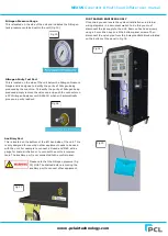
Page 9: ...Test Port This is located on the side of the unit below the Nitrogen Pressure Gauge and is designed to identify the purity of Nitrogen being produced by the machine To identify the purity of Nitrogen...

Page 10: ...move hose from tyre and allow inflator to reset Change connector to OPEN END type E6 Pressure sensor drift out New sensor required Refer to authorised repairer E8 Pressure sensor disconnected from PCB...

Page 11: ...d normal use and service of the unit and upon strict compliance by customer with all of PCL instructions and recommendations for installation operation and maintenance The Limited Warranty does not ap...

Page 12: ...2004 108 EC EMC directive confirmed by report No 10655 TR 1 73 23 EEC LOW Voltage Directive as amended by 93 68 EEC Emission EN 61000 6 3 2007 Electromagnetic compatibility Generic standards EN 55016...

Page 13: ...r die Anweisungen der Bedienungsanleitung die Etiketten Warnhinweise usw lesen verstehen und befolgen Bitte lesen Sie diese Bedienungsanleitung und bewahren Sie sie auf Lesen Sie die Anleitung sorgf l...

Page 14: ...n Betrieb mit der installierten Erdleitung ausgelegt Gem Klasse 1 Basisisolierung in Verbindung mit Schutzerdung Kalibrierung und Genauigkeit Die Genauigkeit unserer digitalen Ger te bei Freigabe ab W...

Page 15: ...n mitgelieferten Schrauben und Unterlegscheiben Abb 2 Die beiden Halterungen mit Schlitz sind bereits am Filter vorbefestigt Abb 3 3 Befestigung der Druckluftleitung an der Filtereinheit Leitung A wir...

Page 16: ...Beachten Sie bitte dass die N6 Version eine Kombi Filtereinheit hat 2 Schlie en Sie das Netzkabel an die IEC Buchse auf der R ckseite des Ger tegeh uses an wie in Abb 8 gezeigt 3 Schalten Sie den Ein...

Page 17: ...markierten Schlauch an den passenden Reifen anschlie en Blau markierte Schl uche f r die Vorderreifen Wei markierte Schl uche f r die Hinterreifen Automatisches Ablassen der Luft mit den zwei Ablassz...

Page 18: ...Dr cken der Tasten oder lassen sich diese Parameter anzeigen Die drei Parameter sind unter 1 Parameter genau beschrieben 3 Um einen der Parameter aufzurufen dr cken Sie auf Start dies ffnet die Inhal...

Page 19: ...t wurde entsprechend den grundlegenden Gesundheits und Sicherheitsanforderungen der EU entworfen und gebaut Dieses Produkt kann bei unsachgem er Verwendung gef hrlich sein Kinder d rfen dieses Ger t...

Page 20: ...lterregler Einheit Ventilkappenmulde Schlauchhaken 4 individuelle Auslass ffnungen 90 mm Rollen Ein Ausschalter Hilfsanschluss N2 Tankdruck Kontrollpunkt f r Reinheit des Stickstoffs Griffe Ger teansi...

Page 21: ...er teseite unter dem Stickstoff Druckmessger t und dient der Messung der Reinheit des von der Maschine erzeugten Stickstoffs Entfernen Sie zur Messung der Reinheit des produzierten Stickstoffs einfach...

Page 22: ...llger t zur cksetzen Ersetzen Sie das Verbindungsst ck durch ein Verbindungsst ck mit OFFENEM ENDE E6 Drucksensor weicht ab Neuer Sensor erforderlich Wenden Sie sich an eine befugte Reparaturstelle E8...

Page 23: ...nd Empfehlungen von PCL zur Installation zum Betrieb und zur Wartung durch den Kunden abh ngig Die beschr nkte Garantie gilt nicht f r Ger te oder Teile die durch unsachgem en Umgang Wartung Lagerung...

Page 24: ...mungen der folgenden EG Richtlinien 2004 108 EG EMV Richtlinie best tigt von Bericht Nr 10655 TR 1 73 23 EEG Niederspannungsrichtlinie ge ndert durch 93 68 EEG Emission EN 61000 6 3 2007 EMV Fachgrund...

Reviews: