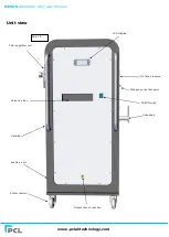
NEXUS
Generator Only user manual
www.pclairtechnology.com
FOR TRAINED ENGINEERS ONLY
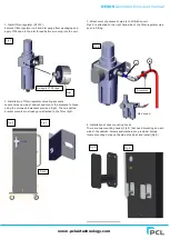
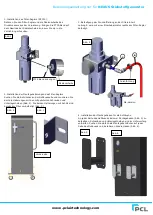
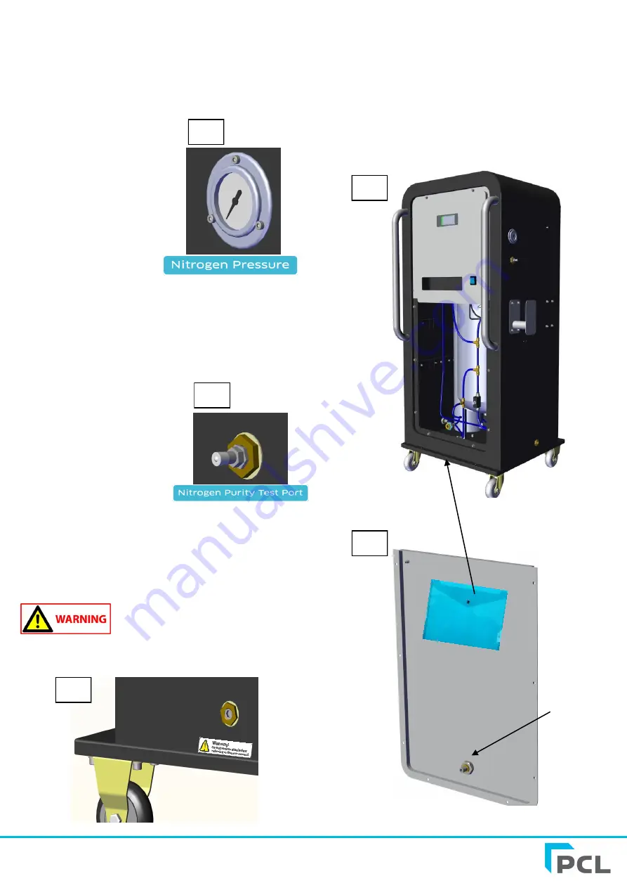
If required you can locate the system installation and internal
wiring diagrams in a document wallet. To do this you must
disconnect the air supply to the unit. Remove hex head screws
using a 5mm Allen key on all the bottom panel screws. Then
disconnect the nylon pipe from the N2 outlet port situated on the
bottom of the panel in Fig 18.
Fig 17
Fig 18
Fig 19
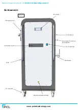
Internal output
pipe connection
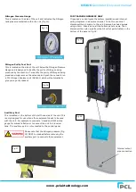
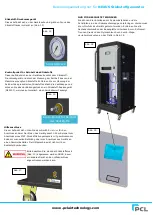
Nitrogen Pressure Gauge
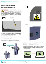
This is located on the side of the unit and indicates the Nitrogen
tank pressure contained within the unit (Fig 15).
Fig 15
Nitrogen Purity Test Port
This is located on the side of the unit below the Nitrogen Pressure
Gauge and is designed to identify the purity of Nitrogen being
produced by the machine. To identify the purity of Nitrogen being
produced simply remove the valve cap and push the connector on
a PCL Nitrogen Analyser unit (N2A001) which will automatically
give you a purity readout.
Fig 16
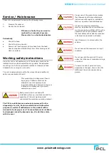
Auxilliary Port
This is located on the bottom of the left hand side of the unit. This
is only designed for use when other equipment needs to be used
with the unit. For example to connect a ‘closed end’ MK3 airline
gauge for manual inflation or to connect the unit to a receiver
tank. The auxiliary port is not connected to the control panel.
Please note that the Nitrogen pressure (Fig
15) MUST be drained before removing the
auxiliary port to connect other equipment.


