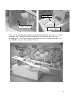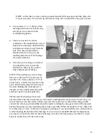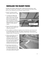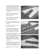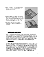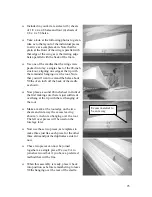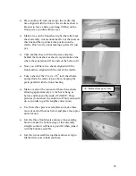
NOTE: At this time you may want to go ahead and bolt the nose gear unit into place but
it is not necessary. You can set up the nose steering servo without the nose gear in place.
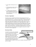
nose
in the
accompanying photos.
the
the fuselage
for proper clearance.
ed
ol
lines and proceed as follows.
of
le
nd make up the two pull-pull lines.
u
re
tening it to allow for fine-tuning. Use thin CA on all
knots to ensure they will not come loose.
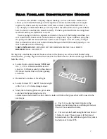
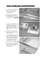
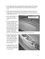
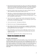
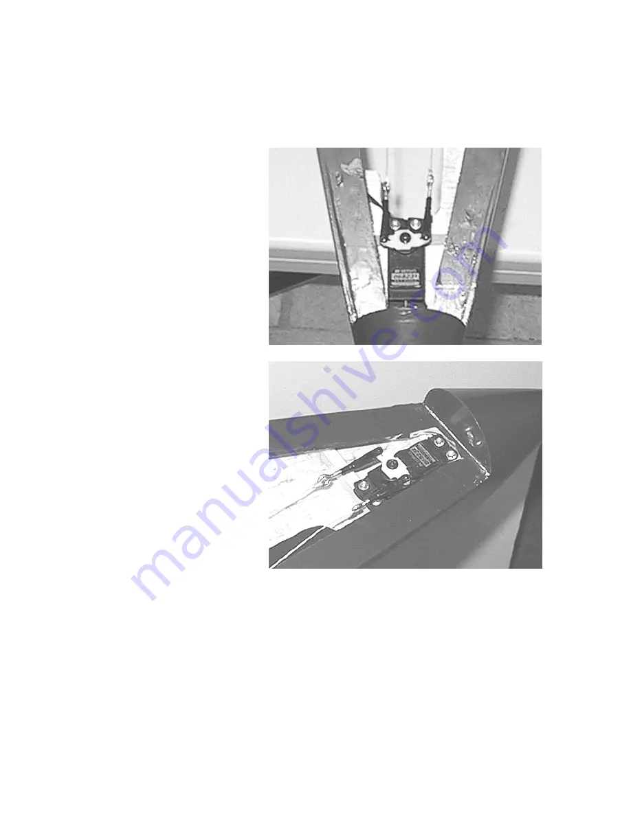
Cut sections of ¼ x ½ Spruce from
the supplied stock to mount the
steering servo as shown
The servo needs to be on the
centerline of the model when viewed
from above and nearly flush with the
cockpit level when viewed from
side. Also keep in mind that a
standard size servo may be just
touching the bottom of
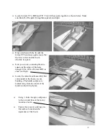
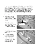
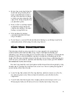
The nose gear steering is activat
via pull-pull set up. Locate the
materials to make up the contr
NOTE: When setting up your steering,
first screw the four 2-56 eyelet screws
into the 2-56 clevises about a 1/16
th
of
an inch only. Connect the clevises to the
servo arm and steering arm at the top
the strut. Holding the strut and servo
straight, use the supplied steering cab
a
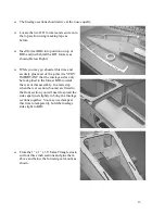
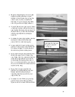
TIP: Remember that these lines will
stretch a little when first used and you will need to read adjust the connections. This is why yo
do not want to screw the clevises all the way onto the eyelet screws when first setting up this
control run. Also keep in mind that when the model is rolling the nose gear strut will be pressed
backwards against its stop, tightening these lines somewhat. When the model is at rest, there will
be a little play or “slop” in the lines so adjust accordingly. You can install the servo either befo
or after sheeting the bottom of the fuselage. If you run out of available threads for adjustment,
you may tie a knot in the Kevlar thus shor
14


