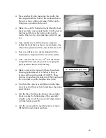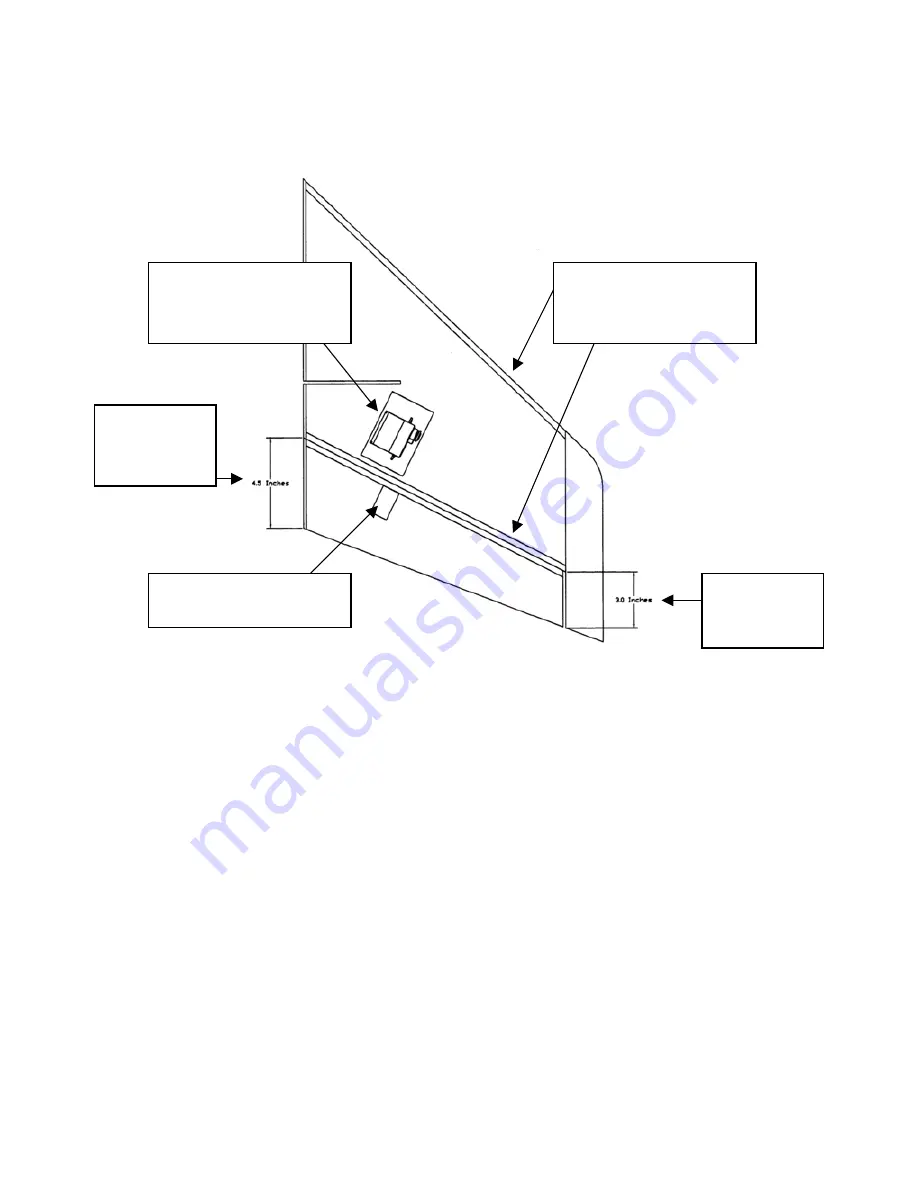
We will give you the measurements for the hinge line then you will add ¼ front and rear
and make marks top and bottom the cut away the control surface and finish the edges to
the lines you have drawn.
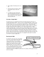
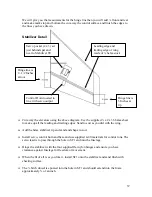
Stabilizer Detail
Servo pocket (2 x 3) set
just behind spar and
next to Stabilizer TE
Leading edge and
trailing edge of wing
made of ¼ balsa stock
Hinge line is
4 –1/2 Inches
at root
Control Horn located in
line with servo output
Hinge line is
3 Inches at
tip
Cut away the elevators using the above diagram. Use the supplied ¼ x 2 x 36 balsa sheet
to make up all the leading and trailing edges. Sand to suit as you did with the wing.
Add the balsa stabilizer tip and sand and shape to suit.
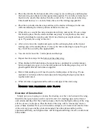
Install servo, control horn and base and use supplied 4-40 materials for control runs. The
servo lead is to pass through the hole in SF1 and into the fuselage.
Hinge the stabilizer with the four supplied flat nylon hinges and ensure you have
clearance against fuselage for freedom of movement.
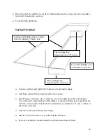
When the fit of all is as you like it, install SF1 onto the stabilizer and sand flush with
sheeting surface.
The ¼ birch dowel is epoxied into the hole in SF1 and should extend into the foam
approximately ¾ of an inch.
37

