2
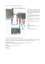
SCENARIO 1: MAX PRO I, SE3 and RDS MAX v1.0 (simple)
The advantage of this setup is its obvious
simplicity. You don’t even have to solder; the only
exception is the positive supply voltage of 12V,
which is really simple. If you are doing this with
the enclosed version of RDS MAX, you don’t even
have to solder anything since there is a connector
for the power supply.
While this setup generally works very well it does
have one small disadvantage. Depending on the
audio content there could be a bit of jitter on the
RDS data carrier.
We’d like to point out here that you should keep
the wires short and mount this setup in enclosure or
separate enclosures.
Install a jumper on J5, place it to the right away
from the edge of the PCB.
Advantages:
-Simple
-Pilot is extracted automatically
-No alignment necessary (when used with PCS
transmitters)
Disadvantages:
-Audio can cause a bit of RDS pilot jitter
SCENARIO 2: MAX PRO I, SE3 and RDS MAX v1.0 (advanced)
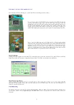
If you know how to install an extra cable for the pilot, this is definitely worth doing. The above connections from scenario 1 stay in place
with scenario 2. The only difference is in a way in which we extract stereo pilot and send it over to the RDS encoder. This is now done via a
dedicated cable. The reason for this is the above mentioned jitter on the pilot. Here’s what you have to do to set this up:
-Connect all cables as shown above
-Connect a short coaxial audio cable from C23 on SE3 (stereo encoder pilot) to the J4 on RDS MAX V1.0.
-Install a jumper on J5, place it to the left towards the edge of the PCB
Advantages:
-No alignment necessary (when used with PCS transmitters)
-Better signal quality
Disadvantages:
-A bit more complex


