VC-M-1
Installation, Operation & Maintenance Manual
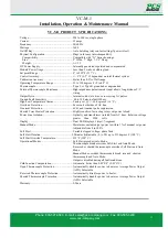
VC-M-1 PRODUCT SPECIFICATIONS:
Voltage ............................................................... 208 to 240vac, single phase
Current ............................................................... 15 amps
Frequency ........................................................... 50/60 Hz
Wattage .............................................................. 3600
On/Off Key......................................................... Auto Latching (stays on last setting if power is lost)
Physical Configuration ....................................... Plugs in for easy interchangeability
Compatibility .................................................. Compatible with “G” Series housings
Size................................................................. 2” Wide, 7” High, 7-1/2” Deep,
Weight .......................................................... .. 1-1/2 #
DC Power Supply ............................................... Internally generated regulated and compensated
Module Power Usage.......................................... Less than 5 watts, excluding load
Set point Range .................................................. 0
o
to 999
o
F (537
o
C)
Control Accuracy................................................ +/- 1
o
F (0.5
o
C) dependent on total thermal system
Calibration Accuracy .......................................... Better than 0.2% of full range
Operating Temperature Range ............................ 32 to 120 degrees F (0 to 48° C)
Thermocouple ..................................................... Type J, or Type K grounded or ungrounded
External Thermocouple Resistance ..................... High impedance potentiometer input allows long distance T/C
wiring
Output Drive ....................................................... Internal solid-state triac, zero crossing AC pulses
Ground Fault Sensitivity ...................................... 60 to 180 mA, default 120 mv.
High/Low Temperature Alarm ............................ Factory set @ +/- 30 degrees F (16° C)
Overload Protection ............................................ Fuses on both sides of AC line
Transient Protection ............................................ dv/dt and transient pulse suppression
Shorted Triac Heater Protection ......................... Highly sensitive, fast acting relays cut power to load
Power Line Isolation........................................... Optically and transformer isolated from AC lines. Isolation voltage
greater than 2500 volts
Display ............................................................... Dual LED displays, 3-digit, 7-segment
Manual Mode ..................................................... Maintains constant output power to within 1% of manual set power.
Adjustable from 0 to 100%
Soft Start ............................................................ Variable stepped voltage, phase fired
Soft Start Duration.............................................. 5 Minutes (Adjustable - 0 to 20) up to 212 degrees F (100° C)
Soft Start Override Temperature ......................... 212
o
F (100° C)
Operational Modes ............................................. Soft Start precedes Auto Mode.
Thermocouple break overrides Soft Start and Auto Mode.
Reversed or shorted thermocouple overrides Soft Start and Auto
Mode.
Manual Mode overrides thermocouple break, reversed, shorted
thermocouple and Auto Mode.
Output is disabled during all fault conditions.
Cold Junction Compensation .............................. Automatic, better than 0.02
o
F/F
o
(0.01
o
C/C)
Open Thermocouple Protection .......................... Automatically disables power to heater or Average Power Output
(APO). Selectable
Reversed Thermocouple Protection .................... Automatically disables power to heater.
Shorted Thermocouple Protection ...................... Automatically disables power to heater or Average Power Output
(APO). Selectable
Warranty.............................................................2-Years
Phone: 800-521-0546 E-mail: sales@pcs-company.com Fax: 800-505-3299
www.pcs-company.com
11


