DRAFT DRAFT
page
18
page
11
b Avoid putting weight on the footrests, as the chair may tip forward.
Pneumatic Tires
WARNING —
Proper infl ation extends the life of your tires and makes your chair easier to use.
1 Do not use this chair if any of the tires is under- or overinfl ated. Check weekly for proper infl ation
level, as listed on the tire sidewall.
2 Low pressure in a rear tire may cause the wheel lock on that side to slip and allow the wheel to turn
when you do not expect it.
3 Low pressure in any of the tires may cause the chair to veer to one side and result in a loss of control.
4 Over-infl ated tires may burst.
Quick-Release Axles
WARNING
1 Do not use this chair UNLESS you are sure that both quickrelease rear axles are locked. An unlocked
axle may come off during use and cause a fall.
2 An axle is not locked until the quick-release button pops out fully. An unlocked axle may come off
during use, resulting in a fall, tip-over or loss of control and cause severe injury to the rider or others.
Rear Wheels
WARNING —
A change in set-up of the rear wheels will aff ect the center of balance of your chair.
1 The farther you move the rear axles FORWARD, the more likely it is that your chair will tip over
backward.
2 Consult your doctor, nurse or therapist to fi nd the best rear axle set-up for your chair. Do not change
the set-up UNLESS you are sure you are not at risk to tip over.
3 Adjust the rear wheel locks after you make any change to the rear axles.
a If you fail to do so, the locks may not work.
b Make sure lock arms embed in tires at least 1/8 inch when locked.
Upholstery Fabric
WARNING
1. Replace worn or torn fabric of seat and seat back as soon as you can. If you fail to do so, the seat may
fail.
2 Sling fabric will weaken with age and use. Look for fraying or thin spots, or stretching of fabrics at
rivet holes.
3 “Dropping down” into your chair will weaken fabric and result in the need to inspect and replace the
seat more often.
4 Be aware that laundering or excess moisture will reduce fl ame retardation of the fabric.
Center of Gravity/Wheel Position
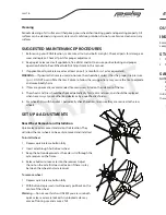
The rear wheel axle location is preset at the factory. Adjustments are possible by moving the axles and
camber tube assembly forward or backwards. To adjust the position,. Place the camber tube at the desired
position, ensure that the camber tube assembly is equally place distance on both sides by measuring
from the camber tube to the rear of the wheelchair, and then fi rmly tighten the bolts.
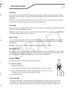
To adjust wheel position
1 Using the 6mm allen key, loosen the M8 socket head bolts
on the bottom of the axle housing/camber tube until it is
possible to slide the assembly forwards and back.
2 Place the camber tube at the desired position, ensure that
the camber tube assembly is equally set on both sides by
measuring from the camber tube to the rear of the wheelchair.
3 Re-tighten the socket head bolts.
Warning
— Camber tube adjustment may increase the tendency
of elevation to tip over either forwards or backwards. The use
of anti-tip devices are strongly recommended to avoid accidents or injury.
Camber Angle
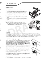
Your Elevation comes standard with a patented camber angle
adjustment.
To adjust camber angle
1 Remove the rear wheels.
2 Remove the camber blocks from the camber tube
assembly by removing the two M8 socket head bolts.
3 To set the camber angle remove M6 button head bolt.
4 Using the chart as reference install the recommended
number of washers on M6 button head for desired camber
angle and re-install onto block. (Spare camber washer are
supplied with chair.)
5 Re-install the camber block to the frame and camber tube
assembly.
6 Place the camber tube at the desired position, ensure that
the camber tube assembly is equally set on both sides
by measuring from the camber tube to the rear of the
wheelchair.
7 Re-tighten the M8 socket head bolts.
Front Casters
The size of the front castors depends on the occupant’s preference. Casters and forks are matched to
the size of the rear wheels and should not be changed or adjusted without consulting an authorized
technician.
Camber
Angle
Number of
Spacers
8
0
6
1
4
2
2
3
0
4
Camber Angle
Spacers


