Communication
Systems Inc.
MODEL PDI-Z13TV SERIES
13”ARM MOUNTED COLOR TV (WR) WIRED REMOTE
Page 1 of 5
Better Solutions Are Within Reach
™
INSTALLATION & SAFETY INSTRUCTIONS
PDI Communication Systems, Inc. 40 Greenwood Lane Springboro, Ohio 45066 USA PH +1-937-743-6010 FX +1 -937-743-5664
PD 196-011 Rev 3
CAUTION
This symbol indicates that dangerous voltage
constituting a risk of electric shock is present
within this unit.
RISK OF ELECTRIC SHOCK,
DO
NOT OPEN!
This symbol indicates that there are important
operating and maintenance instructions in the
literature accompanying this unit.
CAUTION: TO REDUCE THE RISK OF ELECTRIC SHOCK, DO NOT
REMOVE COVER. NO USER SERVICEABLE PARTS INSIDE. REFER
SERVICING TO QUALIFIED SERVICE PERSONNEL
THIS INSTALLATION SHOULD BE MADE BY A QUALIFIED SERVICE PERSON AND SHOULD CONFORM TO ALL LOCAL CODES.
READ AND FOLLOW THE SAFETY INSTRUCTIONS BEFORE ATTEMPTING THIS INSTALLATION.
Note to CATV installer
. This reminder is provided to call the CATV system installer’s attention to Article 820-40 of the NEC that provides
guidelines for proper grounding and, in particular, specifies that the cable ground shall be connected to the grounding system of the building,
as close to the point of cable entry into the room as practical.
WARNING:OXYGEN ENVIRONMENT
DO NOT use
in an oxygen tent or oxygen chanber. Such use may
cause a fire hazard.
WARNING:
To avoid the hazards of fire or electric
shock, DO NOT expose this TV to rain or moisture.
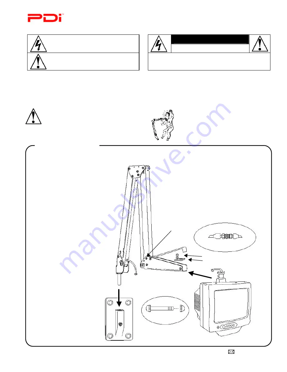
DANGER: ARM RECOIL HAZARD
The safety
brake pin must remain in the SAFETY BRAKE PIN
HOLE whenever the television set is removed from
the arm or when the arm is removed from the wall
bracket to prevent the arm from springing open.
This TV is designed to mount on a model PDI-405 suspension arm. Due to the TV’s weight and size, mounting on any other arm is NOT
recommended.
1. Place the arm’s base pin into
the wall bracket.
2. Open the nose cover and
remove the retainer plate.
3. Insert the TV swivel completely
in the clevis. Reinstall the
retainer plate. Replace the lock
washer and nut, and tighten
with a wrench.
4. The cable from the arm should
be joined with the television
cable, wrench tightened, and
the connection covered by
sliding the plastic boot sections
into mating position.
5. Position the cover in the front
and line up the cover pin holes.
Remove the safety brake pin
from the parking brake hole and
place it in the cover pin hole.
Tighten nut on safety brake pin.
6. Connect the coaxial cable at the
base of the arm to the wall
bracket “F” fitting. Wrench
tighten.
7. This Television for use only with
UL listed power supply maked
to indicate use with this
television.
INSTALL TV ON ARM
TO ARM TO TV
CABLE DETAIL
SAFETY BRAKE PIN
DETAIL
Acorn Nut & Lock Washer
Retainer Plate
Safety Brake
Pin Hole


