Color Monitor Networking________________________________________________________
Ctrl Nr: PM375103 Revision: 003
11
2.2.1
Modbus RTU Ports
The Color Monitor has four (4) paralleled Modbus ports:
•
J1 and J3 are header/plug connections for connecting to most devices.
o
J1 is the upstream port.
o
J3 is the downstream port.
•
J2 and J4 accept standard RJ12 phone cable plugs for connection to an M4G PDU
board.
o
J2 is the upstream port.
o
J4 is the downstream port.
The Modbus RTU interface is isolated, and pin designations are given in Table 1:
Pin
J1, J3
J2 (for RJ12 plugs)
J4 (for RJ12 plugs)
1
Ground
Not used
Not used
2
RX-
RX-
TX-
3
RX+
TX-
RX-
4
TX-
RX+
TX+
5
TX+
TX+
RX+
6
NA
Ground
Ground
Table 1 Pin-Out for Modbus Headers
2.2.2
Modbus RTU 2-Wire vs. 4-Wire Configuration
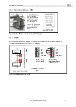
PDI devices have two (2) jumpers near their Modbus ports for configuring 2-wire vs. 4-wire Modbus
RTU (see Figure 4). The
Monitor’s 2-wire configuration jumpers are W1 and W2 (upstream) and W3
and W4 (downstream). Upstream and downstream chains can be differently configured.
For 2-wire configuration:
•
At least one device in a device chain must have both jumpers jumped on its Modbus
connection. If any device in the chain has jumpers installed for 2-wire, all of the device
chain is 2-wire. To avoid confusion when troubleshooting, all of the devices in the chain
should be jumped in the same way.
•
TX+ or RX+ on the Monitor (either one, because the on-board 2-wire jumpers short them
together) wires to TX+ or RX+ on downstream devices.
•
TX- or RX- on the Monitor wires to TX- or RX- on downstream devices.
•
The + and - signal wires should comprise of a (twisted) wire pair residing in the same
shield.
For 4-wire configuration:
•
All of these jumpers must be removed from every device in the chain.
•
TX+ on the
Monitor’s PCB or on the customer Building Management System (BMS) wires
to RX+ on a device PCB (see Figure 5).
•
TX- from the Monitor or BMS wires to RX- on device PCB (see Figure 5).
•
A second pair of wires connects the other pair of TX+ / RX+ & TX- / RX-.
•
The TX+ & TX- going to the RX+ & RX- should be in the same shield. Do not run the +'s
in one shield and the -'s in another. Doing so may lead to sporadic communication.


