WaveStar Color Monitor_____________________________________________________________
Ctrl Nr: PM375103 Revision: 003
18
3.2
Network Setup
Note: Improper configuration of a WaveStar Color Monitor may conflict with other monitors or
devices on the network.
3.2.1
Downstream Modbus Device Chain Setup
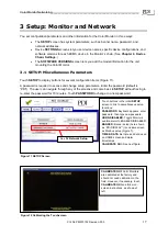
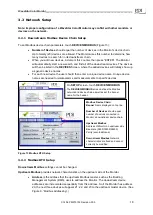
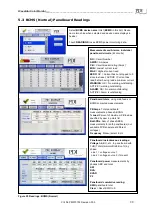
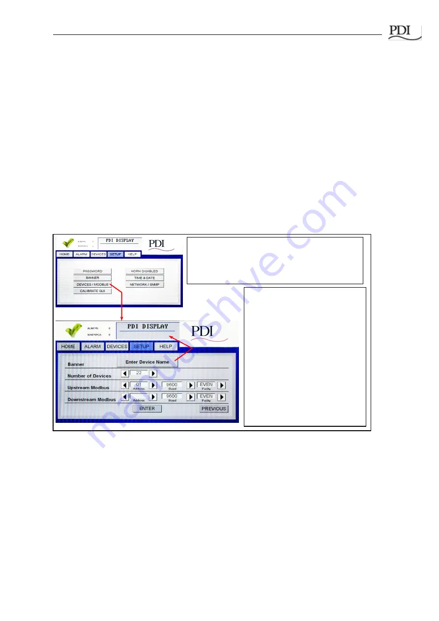
To set Modbus device chain parameters, touch
DEVICES/MODBUS
(Figure 13):
•
Number of Devices
should equal the number of devices in the Monitor’s device chain.
Up to twenty (20) devices are allowed. The Monitor uses this number to determine how
many devices to search for in its downstream chain.
•
When you add new devices, increment this counter, then press
“ENTER”. The Monitor
will automatically start a new search and find all of the downstream devices. The devices
will then be listed in the
DEVICES
Screen, where the added devices will initially show up
as generic device names.
•
For each new device the user should then enter a unique device name. Unique device
names are needed to isolate alarms and measurements to specific devices.
3.2.2
Modbus RTU Setup
Downstream Modbus
settings cannot be changed.
Upstream Modbus
provides network characteristics on the upstream side of the Monitor.
•
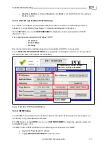
Address
is the address that the upstream Modbus master, such as the Building
Management System (BMS), uses to address the Monitor. The downstream device
addresses are incremented sequentially from this address. So if the Monitor has address
20, the next three devices will appear 21, 22, and 23 to the upstream master device. (See
F
igure 9, “Modbus Addressing”.)
Modbus Device Chain:
Banner
Name displayed on top line.
Number of Devices
should equal
number of devices connected in
Monitor’s downstream device chain.
Upstream Modbus
:
Address of Monitor on upstream side
Baud rate (9600/19200/38400)
Parity (even/odd/none)
Downstream Modbus
Network
characteristics are fixed and cannot
currently be modified.
On
SETUP
screen, touch
DEVICES/MODBUS
.
The
DEVICES/MODBUS
screen defines the Modbus
network and device chain as well as set the banner
name for the header.
Figure 13 Modbus RTU Setup


