Color Monitor Networking________________________________________________________
Ctrl Nr: PM375103 Revision: 003
19
•
Upstream Modbus
settings for
Baud
rate and
Parity
must match those for the upstream
Modbus master.
3.2.3
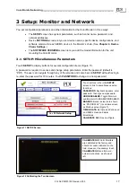
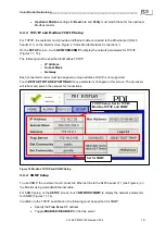
TCP/IP and Modbus TCP/IP Setup
For TCP/IP, the customer must provide an Ethernet cable connected to the Ethernet port (RJ45
header J11) on the Monitor. (See Figure
4, “Color Monitor Network Connections”.)
On the
SETUP
screen, touch
NETWORK/SNMP
to display the network parameters for TCP/IP
(Figures 11, 14)).
The following must be specified for Modbus TCP/IP:
o
IP Address
o
Subnet Mask
o
Gateway
Each connected monitor must be assigned a unique address. DHCP is not supported.
Touch
RESTART WITH NEW SETTINGS
if any parameter is changed on this screen. The processor
will reboot and search the network for connections.
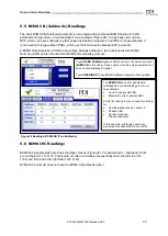
Figure 14 Modbus TCP/IP and SNMP Setup
3.2.4
SNMP Setup
To use SNMP, the customer must connect an Ethernet link to the RJ45 header J11 (see Figure 4) on
the Monitor using a standard Ethernet cable.
For SNMP setup, on the
SETUP
screen, touch
NETWORK/SNMP
to display the network parameters
for SNMP (Figures 11, 14).
In addition to the TCP/IP specification, the following must be specified for SNMP:
•
Specify the
Trap Server
IP address
•
Toggle
ENABLED/DISABLED
for the trap server.
TCP/IP Setup: Set for TCP/IP,
Modbus TCP/IP, and SNMP
Set for SNMP


