56
c. Push button “
UP”
and the Red Button beside the oil-water separator as
Fig. 45
to fill
the oil into both secondly cylinders until it is full (to the highest position).
d. Turn both handle of the shutoff valves to normal working position
(See Fig. 46)
,
push
button
“Down” ,
the lift start to be lowered (If the lift can’t be lowered down,
turning the handle lever of one valve to oil filling position shown as
Fig. 47,
then
quickly turn the handle lever to normal working position, and adjusting another
valve with the same way), then the lift can be lowered. Lower the lift to the lowest
position.
e. Repeat the above procedure
a
to
d
more times, bleeding the air in the cylinder then
the lift would be synchronous worked.
3. Test run
Check the height limit switch, the hose and fitting connection, and do test run. The
lift must be tested run and checked carefully before in use.
VI. OPERATION INSTRUCTIONS
To lift vehicle
1. Keep clean of site near the lift, and down the lift to the lowest position.
2. Drive vehicle on the platforms and pull the brake.
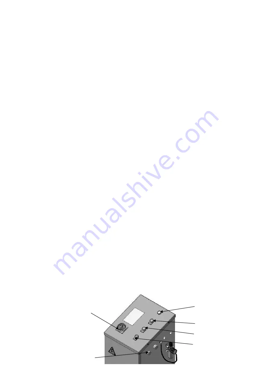
3. Turn on the power and push the button “
Up”
, raise the lift to the working position.
Note:
make sure the vehicle is steady when the lift is rising
4. Push the button
“Lock”
, lock the lift in the safety device. Make sure the safety
device is locked in the same height.
To lower vehicle
1. Be sure clear of around and under the lift, only leaving operator in lift area.
2. Push the button “
Down”,
the lift is lowered continually and stopped at the height
600mm from ground. Keep feet clear off lift, push button “
DOWN”
while push the
Lowering Alarm Button(black)
at the side of control cabinet, the lift is lowered to
ground with alarm tone;
3. Drive away the vehicle when the lift is lowered to the lowest position.
4. Turn off the power.
Power switch
Power indicator
LOCK
DOWN
UP
Lowering Alarm Button
(black)
Fig. 48
29
Summary of Contents for AMGO PX12
Page 1: ...PX12 PX12A X550 X550A...
Page 25: ...50 IV EXPLODED VIEW MODEL PX12A X550A Optional Turnplate Fig 40 95 23...
Page 26: ...51 MODEL PX12 X550 Fig 41 24...
Page 27: ...52 CYLINDERS Fig 42 Add grease to lubricate regularly Add grease to lubricate regularly 25...
Page 28: ...53 CONTROL CABINET Fig 43 26...
Page 29: ...54 PEAK ELECTRIC POWER UNIT 220V 50HZ 1Phase 380V 50HZ 3 Phase Fig 44 27...
Page 41: ...72115304 01 2017...


