background image

NM360L- Nitrogen Gas Generator

UM – NM360L  

With the Generator installed as described earlier. Disconnect the Nitrogen Outlet 
connection to allow the generator to vent to atmosphere until the unit is stabilized then 
open the air supply. The Generator has been pre-set in the factory to give the specified 
output flow-rate and pressure. Once the Membrane reaches the design pressure the 
Generator will stabilise and produce pure Nitrogen. Maximum purity will be achieved 
after around 1 hour. After this time the generator can be re-connected to the 
application.
The design of the generator is that it will deliver up to rated output flow of Nitrogen at 
100 psig. Should the demand for Nitrogen be less than the rated output flow, or indeed 
should the demand stop the generator will continue to operate without any problems. 
The generator is protected from over-pressure.

Commissioning

Commissioning

8

Summary of Contents for NM360L

Page 1: ...NM360L NITROGEN GAS GENERATOR USER MANUAL UM NM360L 19 Rack ...

Page 2: ...intenance Log 13 14 Pneumatic Diagram Over Dimension 12 Technical Specifications 9 Maintenance Schedule 8 Commissioning 7 Principle of Operation 6 Air Connection 4 4 5 Warranty Statement Safety Notice to Users Declaration of Conformity 3 Document History Page No 2 ...

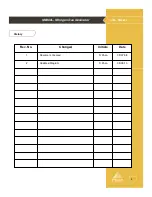
Page 3: ...NM360L Nitrogen Gas Generator UM NM360L History 09 07 08 S Khan Document Created 1 05 05 10 S Khan Updated Diagram 2 Date Initials Changed Rev No 3 ...

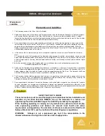
Page 4: ...stomer making a claim in respect of any defect in terms of clause 2 hereof the Customer must 4 1 reasonably satisfy the Company that the Goods have been properly installed commissioned stored serviced and used and without prejudice to the generality of the foregoing that any defect is not the direct or indirect result of lack of repair and or servicing incorrect repair and or servicing use of wron...

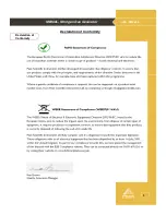
Page 5: ...NM360L Nitrogen Gas Generator UM NM360L Declaration of Conformity Declaration of Conformity 5 ...

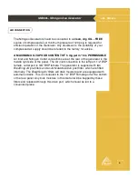
Page 6: ...rogen Outlet connections are at the rear of the generator in the middle right side of the panel The Air inlet connection is the left port 1 2 BSP female outlet port is 3 8 BSP female The generator is supplied with two Breathing Air pre filters and an Activated Carbon post filter which are fitted internally The Breathing Air filters will drain moisture and are equipped with automatic drains This is...

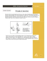
Page 7: ...ed through an Activated Carbon Filter to ensure no carry over of harmful contaminants Peak Scientific Instruments Membrane Generators utilise Hollow Fibre Membrane Technology to efficiently separate Nitrogen from other gases present in ambient air The membrane operates on the principle of selective permeation in that so called Fast gases such as H2O CO2 Oxygen will permeate through the membrane wa...

Page 8: ...rane reaches the design pressure the Generator will stabilise and produce pure Nitrogen Maximum purity will be achieved after around 1 hour After this time the generator can be re connected to the application The design of the generator is that it will deliver up to rated output flow of Nitrogen at 100 psig Should the demand for Nitrogen be less than the rated output flow or indeed should the dema...

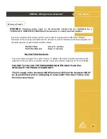
Page 9: ...uipment it should be regularly inspected and serviced as below BA Inlet Filters Every 12 months RAC Filter Elements Every 12 months BA Inlet Filter Elements These should be changed at 12 months intervals In addition filter bowls should be cleaned and the operation of the auto drains should be checked if auto drain requires replacing Part is 02 4485 FAILURE TO FOLLOW THE PRESCRIBED MAINTENANCE PLAN...

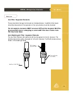
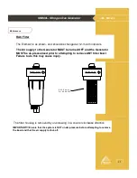
Page 10: ... be turned OFF and the Generator MUST be de pressurised prior to attempting to remove ANY filter bowl Failure to do this may cause injury Inlet Breathing Air Filter Separator Elements The top Filter Element 00 4424 should be changed at 12 month intervals The bottom element should be changed at 12 month intervals The Part Numbers are as shown in the drawings below 10 RAC Element Prt 00 4427 Coalesc...

Page 11: ... turned OFF and the Generator MUST be de pressurised prior to attempting to remove ANY filter bowl Failure to do this may cause injury The filter housing is removed by un screwing in a counter clockwise direction R A C Elem ent P rt 00 4425 IMPORTANT Ensure that the system is NOT under pressure before attempting to remove the bowl and that the air supply is shut off 11 ...

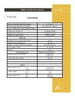
Page 12: ...08 4712 Serviceable Parts List 0 01um Particles 60 minutes Start up time for Purity 360 Litres min ATP Maximum Outlet Flow High Purity Nitrogen 100 psig Maximum Gas Outlet Pressure 8 psig Maximum Pressure Drop Outlet Inlet δP Outlet Gas 1080 l min ATP Minimum Air Inlet Flow Rate 145 psig 10 0 Barg Maximum Air Inlet Pressure 120 psig 8 27 Barg Minimum Air Inlet Pressure Inlet Conditions Free of oil...

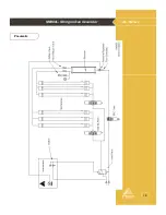
Page 13: ...NM360L Nitrogen Gas Generator UM NM360L Pneumatic 13 ...

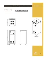
Page 14: ...NM360L Nitrogen Gas Generator UM NM360L Overall Dimensions Overall Dimensions 14 ...

Page 15: ...NM360L Nitrogen Gas Generator UM NM360L Maintenance log Name Date Remarks Work Done Maintenance Log Model NM360L Serial number 15 ...

Page 16: ...NM360L Nitrogen Gas Generator UM NM360L Notes 16 ...

Reviews: