background image

Installation and Operating Handbook

PBU2000 Block Up Converter

Cover Options: 10a, 11

Document Issue v2.10, March 25, 2021

1997

Peak Communications Ltd.

Unit 1, The Woodvale Centre

Woodvale Road

Brighouse

West Yorkshire

HD6 4AB

England

Tel.: +44 (0) 1484 714200

Fax.: +44 (0) 1484 723666

IMPORTANT NOTE: THE INFORMATION AND SPECIFICATIONS CONTAINED IN THIS DOCUMENT

SUPERSEDES ALL PREVIOUSLY PUBLISHED INFORMATION CONCERNING THESE PRODUCTS

PEAK COMMUNICATIONS Ltd maintains a continuing programme of product improvement and therefore

reserves the right to change specifications without notice

PeakManual:v1.52, ODUManual:v1.55, ODUPowerConnectors:v1.26, ODURedundancy:v1.1

Summary of Contents for PBU2000

Page 1: ...and Tel 44 0 1484 714200 Fax 44 0 1484 723666 IMPORTANT NOTE THE INFORMATION AND SPECIFICATIONS CONTAINED IN THIS DOCUMENT SUPERSEDES ALL PREVIOUSLY PUBLISHED INFORMATION CONCERNING THESE PRODUCTS PEA...

Page 2: ......

Page 3: ...e request 12 4 2 2 Remote Local 13 4 2 2 1 Instruction 24 Remote Local Change Request 14 4 2 3 Unit 15 4 2 3 1 Instruction 40 Unit status request 16 4 2 3 2 Instruction 41 Unit status request response...

Page 4: ...Port Status Request 29 4 2 7 2 Instruction 5 Sub Instruction 2 TCP Port Status Response 30 4 2 7 3 Instruction 6 Sub Instruction 2 TCP Port Change Request 31 4 3 Ethernet 31 4 3 1 Webserver 32 4 3 2...

Page 5: ...12 Redundancy status request message format instruction 45 19 4 13 Redundancy status response message format instruction 46 20 4 14 Redundancy change request message format instruction 47 21 4 15 Seri...

Page 6: ...n on installation and use of the PBU2000 unit This manual is of a technical nature and is intended for technicians engineers and service personal The main body of the manual takes the user through the...

Page 7: ...uk To return a Peak Communications product for repair 1 Contact the Peak Communications support department and request a Return Material Authorisation RMA number 2 You will be required to provide to o...

Page 8: ...MAY BE PRESENT AROUND THE POWER SUPPLY AND PRECAUTIONS MUST BE TAKEN THE EQUIPMENT IS MEANT TO BE OPERATED BY TRAINED PERSONNEL ONLY EMC The PBU2000 units have been designed to comply with the followi...

Page 9: ...sheet for the current standard performance or contact technical support for specific technical enquiries 1 2 Chassis The unit is housed in a sealed die cast aluminium box See Appendix A for the dimens...

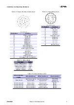
Page 10: ...pin when shorted to Ground will flash the main unit LED for 5 seconds after this time the unit will restart with the static Ethernet IP settings as shown in table 1 1 Note that the ethernet reset pin...

Page 11: ...e release 0 5mS Table 1 4 Redundancy pinout 12 Way circular connector Pin Number Function A CAN Bus low B Ground C Power A D Power B E Ground F CAN Bus high G Tellback A H Tellback B J Not used K Not...

Page 12: ...status LED shows the status of the PBU2000 unit Table 1 6 shows the different LED colours and their associated status meaning Table 1 6 Status LED Colour Status Amber OK and Offline Green OK and Onli...

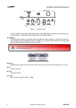
Page 13: ...utput of the unit is a N Type socket marked RF Out Check out all cables for shorts before connecting and ensure the connections are weatherproofed DC must not be introduced to the RF input or output c...

Page 14: ...the changeover option via one of the remote interfaces 3 2 1 for 2 Redundancy For 2 for 1 switched redundant operation a trio of PBU2000 units are required along with an T2000HR Ka or equivalent for r...

Page 15: ...ntrol the PBU2000 unit 4 1 Serial Communications RS232 RS485 The PBU2000 unit is capable of being controlled remotely using the P7xxx protocol format as described in section 4 2 through the RS232 485...

Page 16: ...wise stated Table 4 1 P7xxx protocol Message byte no Set value example Length bytes Description 1 02 1 STX Start of message character 02 2 n 1 Number of bytes Character defining how many characters ar...

Page 17: ...he unit to accept changes made via the remote control it must be placed in REMOTE mode If the unit doesn t have any band attenuation options fitted then the attenuation sections in these messages are...

Page 18: ...able 4 3 Device status request message format instruction 20 Message byte no Set value example Length bytes Description 1 02 1 STX 2 7 1 Number of bytes 3 32 1 Unit address 4 20 1 Instruction number 5...

Page 19: ...verter 6 115 11 5dB 4 Band 1 Main attenuation in 0 1dB steps Attenuator only capable of 0 5dB steps 10 115 11 5dB 4 Band 2 attenuation in 0 1dB steps Attenuator only capable of 0 5dB steps 14 1 1 The...

Page 20: ...on 1 02 1 STX 2 16 1 Number of bytes 3 32 1 Unit address 4 22 1 Instruction number 5 B 1 Block up converter 6 115 11 5dB 4 Band 1 Attenuation in 0 1dB steps Attenuator only capable of 0 5dB steps 10 1...

Page 21: ...ocal modes on the PBU2000 When in local mode all statuses can be asked for from the unit however the unit must be in remote mode to allow configuration changes to be accepted Table 4 6 Remote local in...

Page 22: ...Remote Local Change Request message format instruction 24 Message byte no Set value example Length bytes Description 1 02 1 STX 2 7 1 Number of bytes 3 32 1 Unit address 4 24 1 Instruction number 5 R...

Page 23: ...This group of remote messages allow the user to monitor the unit main status part of the PBU2000 unit Table 4 8 Unit instruction list To unit From unit Description 40 Unit status request 41 Unit stat...

Page 24: ...us request Table 4 9 Unit status request message format instruction 40 Message byte no Set value example Length bytes Description 1 02 1 STX 2 6 1 Number of bytes 3 32 1 Unit address 4 40 1 Instructio...

Page 25: ...ess 4 41 1 Instruction number 5 PBU2000 27 Type of unit this is PBU2000 32 01234 5 Serial number 37 0112 34 7 Software version number 44 0 1 Summary alarm 0 Ok 1 Fault 45 0 1 PLO 1 fault 0 Ok 1 Fault...

Page 26: ...hangeable via the remote control as they are too hardware setup related for it to be of any use to do so Unlike some other configuration messages the unit does not have to be in remote mode for these...

Page 27: ...us request Table 4 12 Redundancy status request message format instruction 45 Message byte no Set value example Length bytes Description 1 02 1 STX 2 6 1 Number of bytes 3 32 1 Unit address 4 45 1 Ins...

Page 28: ...uration A B or S when in 1 2 configuration A H or S when in 1 n configuration 9 1 1 Unit priority X when in 1 for 1 configuration or if units are se lected as standby 1 or 2 when in 1 for 2 configurat...

Page 29: ...is selected as either A or B then only the priority can be changed for that particular unit Table 4 14 Redundancy change request message format instruction 47 Message byte no Set value example Length...

Page 30: ...their address baudrate and whether they use RS232 or RS485 communications via a serial message The PBU2000 will change its serial configuration only if all the settings are valid in the message Table...

Page 31: ...rmat instruction 26 Message byte no Set value example Length bytes Description 1 02 1 STX 2 9 1 Number of bytes 3 32 1 Unit address 4 26 1 Instruction number 5 2 1 RS232 RS485 selection 2 RS232 4 RS48...

Page 32: ...nstruction The unit also does not have to be in remote mode for these messages to take affect Care should be taken when using these messages as it is possible to put the unit in a state that one wasn...

Page 33: ...Table 4 18 Ethernet Status Request message format instruction 4 sub instruction 1 Message byte no Set value example Length bytes Description 1 02 1 STX 2 7 1 Number of bytes 3 32 1 Unit address 4 4 1...

Page 34: ...tes 3 32 1 Unit address 4 5 1 Instruction number 5 1 1 Sub instruction 6 1 1 DHCP 0 Disabled 1 Enabled 7 _ 1 Separator character 8 192 168 000 025 15 IPv4 address 23 _ 1 Separator character 24 255 255...

Page 35: ...Message byte no Set value example Length bytes Description 1 02 1 STX 2 74 1 Number of bytes 3 32 1 Unit address 4 6 1 Instruction number 5 1 1 Sub instruction 6 1 1 DHCP 0 Disabled 1 Enabled 7 _ 1 S...

Page 36: ...nstruction The unit also does not have to be in remote mode for these messages to take affect Care should be taken when using these messages as it is possible to put the unit in a state that one wasn...

Page 37: ...Table 4 22 TCP Port Status Request message format instruction 4 sub instruction 2 Message byte no Set value example Length bytes Description 1 02 1 STX 2 7 1 Number of bytes 3 32 1 Unit address 4 4 1...

Page 38: ...mat instruction 5 sub instruction 2 Message byte no Set value example Length bytes Description 1 02 1 STX 2 18 1 Number of bytes 3 32 1 Unit address 4 5 1 Instruction number 5 2 1 Sub instruction 6 04...

Page 39: ...SNMP Due to a lack of front panel on these units it is not possible to display the IP address and other Ethernet settings to the user easily In order to discover the IP address and other Ethernet set...

Page 40: ...be controlled via TCP this involves sending the normal RS232 485 commands to the unit through a TCP port The TCP port to be used is set by the user via one of the remote control interfaces The remote...

Page 41: ...Installation and Operating Handbook Appendix A Mounting Drawings PBU2000 Peak Communications Ltd 33...

Page 42: ...te 1 1 Edition Sheet Date REVISION HISTORY ZONE REV DESCRIPTION DATE APPROVED 1 Created 25 08 2015 NJD 2 Added the width 12 10 2016 NJD 306 00 286 00 112 00 52 00 105 00 MAX R3 00 20 00 POLE MOUNTING...

Reviews: