Installation and Operating Handbook
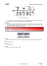
FUSE: 20 x 5mm
2A MAX
Remote/
Alarms
RF
In
Ethernet
RF
Out/
Power/
10MHz
Ref.
Redundancy
Status
Figure 1.1: Connector view
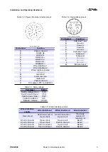
The wired interface pins allow simple band selection of the PBU2000 by shorting the wired interface pins
to Ground table 1.5 shows the pin requirements for the selectable bands.
Redundancy
12 Way circular connector on the chassis with connections as shown in table 1.4. The ’Ethernet reset’ pin,
when shorted to Ground will flash the main unit LED for
≈
5 seconds, after this time the unit will restart
with the static Ethernet IP settings as shown in table 1.1.
Note that the ethernet reset pins must not be connected to any pin other than ground or per
manent damage will occur.
Table 1.1: Ethernet reset settings
Parameter
Setting
IP address
192.168.0.2
Subnet Mask
255.255.255.000
Gateway
192.168.0.1
Ethernet
Sealed RJ45 connector, the cover of which must remain in place to keep the IP rating when not in use.
RF In
NType connector.
RF Out
NType connector.
EXT. Ref
TNC connector, input at 10MHz
±
3dBm.
2
Peak Communications Ltd.
PBU2000
Summary of Contents for PBU2000
Page 2: ......


