Installation and Operating Handbook
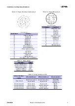
Table 1.2: Power / Remote / Alarms pinout
16 Way male circular
Pin Number
Function
A
Chassis Ground
B
RS232 Rx
C
RS232 Tx
D
RS485 Tx +
E
RS485 Tx
F
RS485 Rx
G
RS485 Rx +
H
Wired interface 1
I
Wired interface 2
K
Wired interface enable
L
Not used
M
Alarm N/C
N
Alarm common
O
Alarm N/O
P
Chassis Ground
R
DC supply (+27V to +36V DC)
Table 1.3: Relay ratings
Parameter
Rating
Switch voltage (max.)
100V
Switch current (max.)
0.5A
Switch power (max.)
10W
Contact resistance
0.2
Ω
Operate / release
0.5mS
Table 1.4: Redundancy pinout
12 Way circular connector
Pin Number
Function
A
CAN Bus™ low
B
Ground
C
Power A
D
Power B
E
Ground
F
CAN Bus™ high
G
Tellback A
H
Tellback B
J
Not used
K
Not used
L
Not used
M
Ethernet reset
Table 1.5: Wired interface control
Wired interface
enable
Wired interface 1
Wired interface 2
Band selected
Open circuit
Short to Ground or
Open circuit
Short to Ground or
Open circuit
Previously
selected or
remotely set
Short to Ground
Open circuit
Open circuit
Band 1
Short to Ground
Open circuit
Short to Ground
Band 1
Short to Ground
Short to Ground
Open circuit
Band 2
Short to Ground
Short to Ground
Short to Ground
Band 2
PBU2000
Peak Communications Ltd.
3
Summary of Contents for PBU2000
Page 2: ......


